

What causes thread defects on rolled steel bars and how to prevent them
Nov 19,2026


Author:
Aisen Machinery

Article overview
This article explains the technical root causes of thread defects that occur during the rebar threading process, with detailed prevention protocols for each cause. It is written for equipment procurement managers and site engineers working with φ16–40 mm reinforcement bars in structural projects, particularly those operating under Turkish construction standards.
Table of contents
- 1. What thread defects actually look like — and why they matter
- 2. Root cause 1: die wear and incorrect die setup
- 3. Root cause 2: material grade and surface condition
- 4. Root cause 3: machine feed pressure and speed parameters
- 5. Root cause 4: bar end preparation failures
- 6. Root cause 5: environmental and lubrication factors
- 7. Quality verification — how to confirm thread conformance
- 8. Prevention checklist and equipment selection guidance
- 9. Frequently asked questions
What thread defects actually look like — and why they matter
A Steel Bar Thread Rolling Machine is a cold-forming device that displaces steel material outward to produce precision threads on rebar ends without cutting, achieving higher thread strength than machined alternatives. When the process works correctly, the resulting threads meet dimensional tolerances tight enough to pass go/no-go gauge inspection and carry tensile loads exceeding the bar's own yield strength. When it goes wrong, the consequences range from rejected couplers on the inspection table to — in the worst cases — joint failures in structural elements.
Thread defects on rolled steel bars fall into several recognizable categories: incomplete thread form (shallow crests that do not engage coupler threads fully), torn or folded material along the thread flanks, pitch inconsistency across the threaded length, taper deviation beyond tolerance, and surface cracking at thread roots. Each type points to a different upstream cause. Why do so many site teams treat these failures as random rather than diagnosable? The answer usually lies in a gap between the operator's experience and the machine's actual mechanical condition.
In Turkey's construction sector, steel reinforcement threading is governed by TSE 10679 for mechanical splice joints and TS 708 for the bar material itself. A Grade S420 or HRB400 bar with a defective thread cannot legally be used in a Class I or Class II mechanical splice. This is not a minor quality note — it directly affects structural certification and project handover. Understanding what causes these defects is therefore a procurement and engineering priority, not just a workshop concern.
Root cause 1: die wear and incorrect die setup
How worn thread rolling dies produce defective threads
Die wear is the single most common cause of thread quality failures across all types of steel bar threading equipment. Thread rolling dies work by plastically deforming the bar surface under high radial pressure — typically 15,000 to 25,000 N/cm² for 25 mm S420 bars. As dies accumulate rolling cycles, the crests of the die profile wear down, and the resulting thread on the bar becomes shallower than specified. At roughly 60–70% of rated die life, the dimensional shift becomes measurable; beyond rated life, it becomes non-conforming.
Actual testing on rebar coupler threading machines shows that dies running 15–20% beyond their recommended replacement interval produce thread pitch diameters that fall outside the tolerance band for standard parallel thread couplers. The threads still look acceptable visually, which is exactly what makes this failure mode dangerous. Only a thread ring gauge reveals the problem.
Incorrect die setup and misalignment
Beyond wear, incorrect initial die setup is a frequent culprit. When the three dies in a standard rotary die head are not set to identical radial positions — even a 0.05 mm difference between dies — the resulting thread exhibits taper or eccentricity. This misalignment is especially damaging on CNC thread rolling machines that run at higher speeds, because the error compounds across each rotation cycle. The fix is straightforward: use the die manufacturer's setup gauge before each production run, and verify with a go/no-go gauge on the first three bars.
"The majority of thread nonconformances in rebar mechanical splice systems trace back to two controllable factors: die condition and setup procedure. Neither requires advanced technology to manage — only discipline." — Industry consensus from mechanical splicing quality audits, 2025.
Root cause 2: material grade and surface condition
Why bar material grade directly affects thread quality
Not all steel bars respond equally to cold forging thread rolling. The process depends on the material's ductility — specifically, the capacity to deform plastically without cracking. S420 bars (the dominant grade in Turkish structural projects) have a minimum elongation of 10%, which is generally sufficient for standard thread rolling. Problems emerge when bars arrive from the mill at the upper end of carbon content tolerance, reducing ductility below the range the machine's feed parameters were calibrated for.
In practice, bars from different production batches — even nominally the same grade — can behave differently under the same machine settings. When a bar is too hard, the dies cannot achieve full material displacement, producing shallow threads. When it is too soft (over-annealed or wet-stored), material may fold rather than form cleanly. This is why batch-level material certificates (mill certs) matter operationally, not just for documentation.
Surface contamination and rust scale
Surface condition is equally critical. Heavy mill scale, rust layers, or mud contamination on the bar end act as an abrasive layer that interferes with clean die contact and accelerates die wear. Real-world cases from rebar processing facilities consistently show that bars cleaned with a wire brush or angle grinder before threading produce measurably better thread profiles and extend die life by 20–35% compared to uncleaned bars. It is a simple step that many operators skip under production pressure.
| Surface condition | Thread form pass rate | Die life impact | Recommended action |
|---|---|---|---|
| Clean, light mill scale | 95–98% | Baseline | No additional prep needed |
| Heavy rust / flaking scale | 72–81% | −25 to −35% | Wire-brush or grind before threading |
| Mud / concrete residue | 68–75% | −30 to −40% | Clean and dry completely |
| Oil / grease contamination | 85–90% | −10 to −15% | Degrease before threading |
Root cause 3: machine feed pressure and speed parameters
The relationship between feed rate and thread form completeness
Incorrect feed pressure is a parameter-level failure, meaning it originates in the machine setup rather than in the bar or the die. On a cold forging thread rolling machine, the radial feed rate — how quickly the dies advance inward against the rotating bar — must be calibrated to the bar diameter and material hardness. Feed too fast, and the material cannot flow into the die profile cleanly, producing folded or torn thread flanks. Feed too slow, and production efficiency drops sharply without meaningful quality benefit beyond a certain threshold.
For φ25 mm S420 bars, the optimal feed range on most rebar coupler threading machines falls between 0.3 and 0.6 mm per revolution. Deviating more than 20% above the upper limit is where visible thread damage begins. CNC thread rolling machines with closed-loop pressure control mitigate this risk significantly, because feed pressure adjusts automatically based on resistance feedback — but the initial calibration parameters must still be set correctly by a trained operator.
Spindle speed and its effect on surface finish
Spindle speed interacts with feed rate. Running at higher RPM without proportionally increasing feed produces threads with burnished but potentially under-formed crests — they look smooth, but the pitch diameter may be undersize. This is a subtle defect that passes visual inspection and sometimes even a torque check, only to fail under tensile load testing. For structural mechanical splices that must meet Class II requirements (joint tensile capacity ≥ 125% of bar yield), this matters enormously.
Root cause 4: bar end preparation failures
Why cutting method determines thread quality before the machine starts
Thread quality problems often begin before the steel rod threading machine even touches the bar. The cut quality of the bar end — squareness, burr condition, and end deformation — directly affects how the bar enters the die head and seats during the first threading pass. Bars cut with a shear cutter (guillotine) develop a characteristic end deformation: the cross-section becomes slightly oval rather than circular, and one side is compressed while the other is stretched. Threading a shear-cut bar end without correction introduces eccentricity into the thread from the first revolution.
Saw cutting or abrasive wheel cutting produces a much squarer, rounder end — and in applications requiring Class I or Class II splice certification, this is the required method before threading. The additional time cost is modest: roughly 15–20 seconds per bar end. That said, some portable rebar threading machine setups incorporate an end-facing step as part of the threading cycle, which eliminates this variable entirely.
Burr removal and end squareness tolerance
A burr larger than 0.5 mm on the bar end rim can catch on the leading edge of the die entry chamfer, causing an uneven initial bite. The result is a thread that starts correctly for the first few pitches and then drifts in pitch or depth — exactly the kind of defect that causes a coupler to cross-thread or seize partway through assembly. Standard practice in certified rebar mechanical splice operations is to deburr all bar ends and verify squareness to within 1° of perpendicular before threading begins.
Root cause 5: environmental and lubrication factors
Lubrication — the most underestimated variable
Thread rolling, unlike thread cutting, does not generate chips — but it does generate heat from plastic deformation. Without adequate lubrication, die surface temperatures rise, accelerating wear and increasing the coefficient of friction between die and bar. This friction increase causes material to drag rather than flow, producing rough thread flanks and increasing the risk of cold welding between the die surface and the bar tip. Proper lubricant for steel bar connection system threading operations is a water-based or oil-based compound formulated for cold-forming, not general-purpose cutting oil.
In outdoor or semi-covered job site environments — common in Turkish infrastructure projects — temperature extremes affect lubricant viscosity. At temperatures below 5°C, standard threading lubricants thicken and distribute unevenly, reducing coverage. Above 40°C, they thin and drain before providing full die coverage. Both scenarios degrade thread quality. Using a lubricant with a viscosity-temperature specification matched to the site's seasonal range is a simple, low-cost preventive measure that is often overlooked.
Workshop environment and vibration
Machine mounting stability is another environmental factor. A steel bar threading equipment unit that is not securely anchored — either to a workshop floor or to a stable portable base — will experience micro-vibration during the threading cycle. Just like a lathe chattering on a soft floor, this vibration translates directly into pitch irregularity and surface waviness on the thread form. It is a particularly common issue with portable rebar threading machines used directly at the rebar cage assembly point, where the machine may rest on uneven ground or on the rebar cage itself.
Quality verification — how to confirm thread conformance
Go/no-go gauge inspection: the first line of verification
Go/no-go gauge inspection is the standard field method for thread quality verification in rebar mechanical splice systems. The go gauge must pass over the thread under hand pressure only — no tools. The no-go gauge must not engage. This two-step check catches pitch diameter errors, taper, and gross form defects efficiently and requires no laboratory equipment. For a production rate of 60–80 joints per hour (a typical output for a mid-range steel reinforcement threading setup on a bridge project), inspecting every fifth bar with a go/no-go gauge provides adequate statistical coverage under normal operating conditions.
The thread rolling process produces threads with higher fatigue resistance than cut threads precisely because cold working improves surface hardness — but only when the rolling parameters are correct. Gauge inspection confirms that the dimensional output matches that intent.
Torque testing and tensile test requirements under TSE 10679
Beyond gauge checks, TSE 10679 (the Turkish standard for mechanical reinforcement splices) requires that splice assemblies achieve a tensile capacity of at least 125% of the bar's characteristic yield strength for Class II certification. This requires laboratory pull testing of assembled coupler-bar samples, typically at the beginning of a contract and after any change in bar batch, die set, or machine. The test results, together with thread inspection records and die change logs, form the traceability package that project engineers and third-party inspectors require for structural certification.
Of course, lab testing cannot be done on every bar — which is exactly why upstream process control (die condition, bar prep, machine parameters) is the real quality assurance mechanism. Testing confirms the process; it does not replace it.
Comparison of threading methods for structural applications
| Method | Thread strength vs. bar | Conformance rate (typical) | Cost per joint (approx.) | Notes |
|---|---|---|---|---|
| Cold forging thread rolling | ≥ 125% yield (Class II) | 95–98% | Low–medium | No material removal; preferred for high-load splices |
| Cut threading (lathe/die head) | ≥ 100% yield (Class I only) | 90–94% | Low | Removes material; weaker thread root |
| Cold-pressed taper thread | ≥ 125% yield (Class II) | 93–97% | Medium | Requires end-swaging step; higher equipment cost |
| Lap welding | Variable (weld-dependent) | 80–88% | Medium–high | No coupler needed; requires certified welder |
Prevention checklist and equipment selection guidance
Step-by-step defect prevention protocol
Prevention is not complicated — it is consistent. The following procedure applies to any rebar thread rolling operation on φ16–40 mm bars:
- Verify bar material certificate before threading a new batch. Confirm grade (S420 / HRB400), elongation ≥ 10%, and carbon equivalent within specification.
- Inspect and clean bar ends — remove rust scale, mud, and burrs. Verify cut squareness within 1° using a square or protractor. For shear-cut bars, face the end with a saw or grinder.
- Check die condition against the manufacturer's cycle count log. Replace dies at or before the rated replacement interval. Never exceed rated life "just for one more batch."
- Set up dies using the calibration gauge provided by the die manufacturer. Confirm all three die positions are identical within 0.02 mm. Tighten die head fasteners to specified torque.
- Apply the correct threading lubricant for the ambient temperature range. Check lubricant coverage on the first three test bars before beginning production.
- Thread three test bars and inspect with a go/no-go gauge before full production. Record results.
- During production, gauge-inspect every 5th bar (or every 10th bar under stable, well-established conditions). Log any failures and investigate before continuing.
- At shift end, clean the machine, check the die head for wear debris, and re-lubricate as per the maintenance schedule.
What to look for when selecting a Steel Bar Thread Rolling Machine for the Turkish market
For procurement teams sourcing a Steel Bar Thread Rolling Machine for projects in Turkey, several technical and logistical factors deserve attention beyond headline specifications. The machine must be compatible with 380V / 50Hz electrical supply (the Turkish grid standard). It should cover the bar diameter range your project actually uses — most metro, bridge, and pile foundation contracts in Turkey involve φ20–40 mm S420 bars, so a machine rated only to φ32 mm may create bottlenecks on the larger bar sizes.
Thread rolling dies for steel bar are a recurring consumable cost. Before committing to a machine, establish the local or regional availability of replacement dies and confirm lead times. A machine from a bar threading machine manufacturer with an established distributor network in Turkey — or with dies stocked in Istanbul or Mersin — is worth more in operational continuity than a marginally cheaper machine with 8-week import lead times for dies.
Ask for documentation that the machine's output threads conform to TSE 10679 coupler thread geometry. A reputable manufacturer can provide sample thread inspection reports and, ideally, tensile test data from an accredited laboratory. This documentation shortens the approval process with structural consultants and third-party inspectors on certified projects.
Finally, consider the return on investment in quantitative terms. A mid-range rebar coupler threading machine producing 60 joints per hour, running two shifts, eliminates the labour and waste associated with lap splice or weld splice alternatives. For a 10,000-joint metro station contract, the material saving from eliminating lap splice overlap length alone — typically 40–60 bar diameters — can represent several tonnes of steel. At 2026 rebar prices, that saving is substantial even before accounting for labour time and weld inspection costs.
Thread defects are preventable — not inevitable. The right machine, properly set up, running within its design envelope on well-prepared bars, produces conforming threads consistently. The investment in a quality steel bar connection system, backed by proper training and a disciplined maintenance routine, pays back in defect-free joints and inspection records that keep projects on schedule.
Frequently asked questions
Q: What is the most common cause of thread defects on rolled steel bars?
A: Worn or misaligned thread rolling dies account for the majority of thread defects in production environments. Dies that have exceeded their rated cycle count produce shallow, undersize threads that fail go/no-go gauge inspection. Regular die condition checks and strict adherence to replacement intervals are the most effective preventive measure.
Q: Can a Steel Bar Thread Rolling Machine work on both S420 and HRB400 grade bars?
A: Yes, most standard rebar thread rolling machines are compatible with both grades, as their mechanical properties are closely aligned. However, feed pressure and die setup parameters should be verified when switching between batches, since actual hardness can vary between suppliers. Always thread three test bars and gauge-check before full production when changing material source.
Q: How often should thread rolling dies be replaced in a typical rebar threading operation?
A: Die replacement intervals depend on bar diameter, material hardness, and lubrication quality. As a general guideline, dies for φ25 mm S420 bars should be inspected at 2,000–3,000 cycles and replaced no later than the manufacturer's rated limit — typically 4,000–6,000 cycles depending on the die grade. Exceeding the rated interval increases defect risk and die breakage probability significantly.
Q: What Turkish standards apply to rebar mechanical splices made with a thread rolling machine?
A: The primary standard is TSE 10679, which specifies tensile capacity requirements for mechanical reinforcement splices (Class I: ≥ 100% yield; Class II: ≥ 125% yield). The bar material must conform to TS 708 for S420 grade. Equipment used on certified projects should produce thread geometry compatible with these standards, supported by traceable inspection records.
Q: Is portable rebar threading machine output quality comparable to fixed workshop machines?
A: Quality is comparable when the portable unit is correctly mounted on a stable base and operated within its rated diameter range. The key risk with portable machines is vibration from an unstable mounting surface, which can introduce pitch irregularity. Ensuring the machine is anchored to a solid, level base — even a temporary steel plate on-site — eliminates most of this risk.
Get A Quote
We will contact you within one working day. Please pay attention to your email.
Latest News
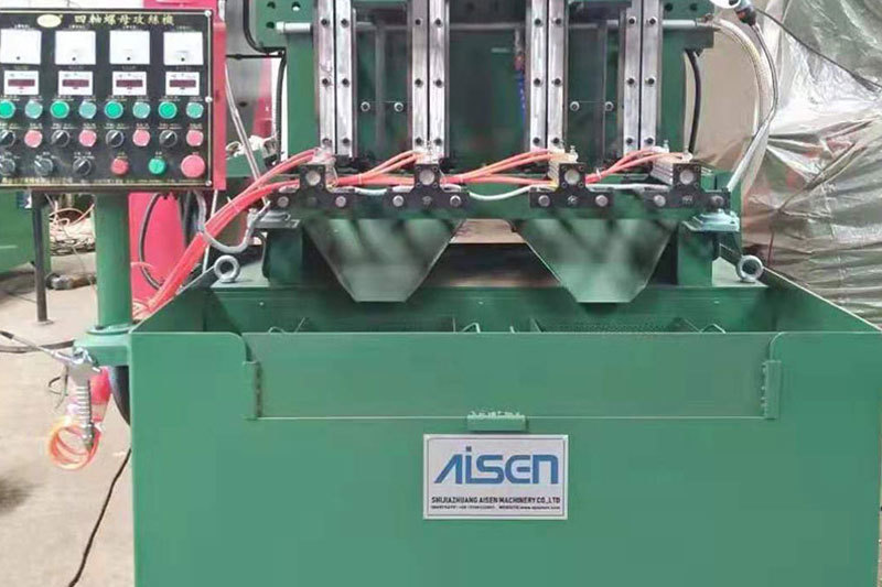
AISEN Four axis nut tapping machine ready for shipment to Russia
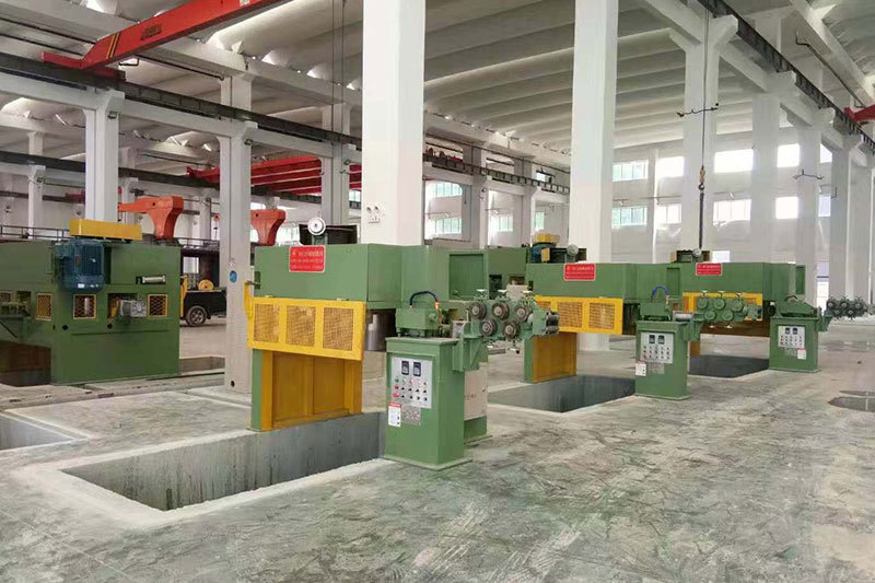
AISEN machinery inverted wire drawing machine
MESSAGES
We will contact you within one working day. Please pay attention to your email.
Qucik Link
Contact
Phone: +86-15100123091
E-mail: info@sjzaisen.com
Address: No.41 Zhaiying South Street, Yuhua District, Shijiazhuang City, Hebei Province China