

Tube drawing machine buyer's guide: specs, features and selection tips
Nov 21,2026


Author:
Aisen Machinery

Article overview
This buyer's guide explains tube drawing machine types, engineering selection criteria, defect troubleshooting, process comparisons, Indian market pricing and ROI calculation — structured for procurement engineers and plant managers at the supplier evaluation stage.
Table of contents
- 1. What is a tube drawing machine and how does it work?
- 2. Types of tube drawing machines: which process fits your application?
- 3. Engineering selection: force, wall reduction and pass schedule calculations
- 4. Die and mandrel design, lubrication and surface quality control
- 5. Common defects in tube drawing: causes, diagnosis and fixes
- 6. Process comparison: tube drawing vs cold rolling, extrusion and rolling
- 7. Key specifications, tolerance standards and compliance checklist
- 8. Indian market buying guide: pricing, GST, lead time and TCO
What is a tube drawing machine and how does it work?
A Tube Drawing Machine is metal forming equipment that pulls a tubular blank through a hardened die — with or without an internal mandrel — to reduce its outer diameter, wall thickness, or both simultaneously, while improving dimensional accuracy and surface finish. The process is performed cold, which means no external heating is applied, and the resulting work-hardening measurably increases tensile strength.
The fundamental mechanics are straightforward. A tube blank (called the mother tube or shell) is first pointed at one end — a step known as pointing or swaging — so it can be threaded through the die aperture. The pointed end is gripped by a draw carriage or chain, which pulls the tube through the die at controlled speed. What actually governs the final dimensions, however, is the relationship between the die angle, the mandrel geometry, and the drawing speed. Get any one of these wrong and you face wall thickness variation, surface scoring or tube fracture.
Understanding the tube drawing process in full — including friction coefficients, redundant work and die pressure distribution — is essential before specifying a machine. The same physics that governs wire drawing applies here, but the addition of an internal mandrel makes tube drawing considerably more complex to control.
Why is tube drawing still the dominant precision tube manufacturing route?
Cold drawing produces tighter tolerances than hot extrusion alone, achieves surface roughness values below Ra 0.8 µm without grinding, and can process a wide range of alloys — steel, stainless, copper, aluminium and titanium. For precision tube drawing applications in hydraulic systems, automotive fuel lines or medical devices, no competing process delivers the same combination of dimensional control and mechanical property enhancement at comparable cost per metre. That is why, despite the rise of cold rolling (Pilger) technology, the draw bench remains the backbone of seamless tube manufacturing in India and globally.
How does a draw bench differ from a coiler-type machine?
Chain-type draw benches — the dominant format in India — handle straight lengths from 3 m to 18 m and pulling forces from 5 tonnes up to 150 tonnes. Coiler-type (bull-block) machines wind the drawn tube onto a reel, suiting small-diameter copper or aluminium tube production. The choice between the two is primarily dictated by tube diameter, wall thickness and the minimum bend radius the material can tolerate without kinking during coiling.
Types of tube drawing machines: which process fits your application?
Five distinct drawing processes exist, each demanding different tooling and machine configurations. Matching the process to your product specification before purchasing equipment is non-negotiable — retrofitting a machine for the wrong process invariably costs more than selecting correctly from the start.
Tube sinking (hollow sinking / empty drawing)
No mandrel is used. The tube is drawn through the die purely by external die contact, reducing OD while wall thickness remains approximately constant (it may thicken slightly at a 24° semi-angle). This is the fastest and cheapest setup, but inner surface quality is uncontrolled. Suitable for OD reduction passes where ID tolerance is not critical, or as an intermediate pass before a mandrel pass.
Fixed mandrel, floating mandrel and moving mandrel (rod drawing)
Fixed plug mandrels are anchored behind the die; they excel at tight wall-thickness tolerances but limit drawing length. Floating mandrels self-position inside the deformation zone — they are the workhorse of seamless tube manufacturing on a cold drawing machine because they allow longer draws without the rod-length constraint. Moving (long rod) mandrels travel with the tube and are stripped afterward; they deliver the best inner surface finish but require a mandrel-stripping bench. For a copper tube drawing machine producing refrigeration coils, floating plugs are almost universally specified. For precision hydraulic steel tubes, moving mandrels are preferred when ID roughness below Ra 0.4 µm is required.
Engineering selection: force, wall reduction and pass schedule calculations
Sizing a tube drawing machine on pulling force alone is insufficient. The correct sequence is to calculate the required drawing force for your worst-case pass, add a safety margin of 1.5×, then select the machine capacity. Here is the step-by-step engineering method used by process engineers at Indian tube mills.
- Define the cross-sectional area reduction (R): R = (A₀ − A₁) / A₀ × 100%, where A₀ and A₁ are the cross-sectional areas of tube wall before and after drawing. Industry guideline: R per pass should not exceed 35% for carbon steel or 25% for stainless steel without intermediate annealing.
- Calculate drawing stress (σ_d): σ_d = σ_f × (1 + µ·cot α) × ln(A₀/A₁), where σ_f is the mean flow stress of the material, µ is the die–tube friction coefficient (typically 0.05–0.12 with soap lubricant), and α is the die semi-angle (typically 8°–15°).
- Determine drawing force (F): F = σ_d × A₁. For example, drawing a 50 mm OD × 4 mm wall carbon steel tube from 56 mm OD with σ_f = 450 MPa, µ = 0.08, α = 10° gives F ≈ 18.5 tonnes. Multiply by 1.5 safety factor → specify minimum 28-tonne capacity machine.
- Plan the pass schedule: Total reduction targets are achieved across multiple passes with intermediate annealing after every 2–3 passes for carbon steel. Each pass reduces OD by 10%–20% and wall by 5%–15%. Document the schedule as a table specifying OD, ID, wall, R (%), and annealing requirement for every pass.
- Verify machine stroke and chain speed: Ensure the bench length accommodates your longest finished tube plus the pointed end overhang. Chain speed range (typically 5–60 m/min on modern machines) must match your productivity target.
"Undersized drawing equipment is the single most common cause of tube fracture and die failure at Indian tube mills. Always calculate the worst-case pass load — not the average — and size the machine accordingly." — Consensus recommendation from tube drawing engineering literature and confirmed through real-world plant assessments.
What tonnage machine do I need for my tube dimensions?
As a quick reference, the table below provides indicative machine capacity requirements for common tube sizes. These values assume carbon steel (σ_f ≈ 450 MPa), µ = 0.08, single floating mandrel pass, and 1.5× safety factor applied.
| Finished OD (mm) | Wall thickness (mm) | Area reduction per pass (%) | Calculated draw force (tonnes) | Recommended machine capacity | Indicative price range (INR, ex-GST) |
|---|---|---|---|---|---|
| 10–25 | 0.5–2.0 | 20–30 | 3–8 | 10-tonne draw bench | ₹8–15 lakh |
| 25–60 | 2.0–5.0 | 20–30 | 12–28 | 30–40-tonne draw bench | ₹30–65 lakh |
| 60–120 | 4.0–10.0 | 15–25 | 35–65 | 80-tonne draw bench | ₹80–140 lakh |
| 120–200 | 8.0–20.0 | 12–20 | 70–110 | 150-tonne draw bench | ₹160–280 lakh |
Die and mandrel design, lubrication and surface quality control
Even the most precisely specified pipe drawing machine delivers poor results without correctly designed tooling and a disciplined pre-treatment protocol. This is the area most frequently underinvested by first-time buyers.
Die (tube drawing die) geometry and material selection
A tube drawing die consists of four zones: the entry bell, the approach (working) angle, the bearing (land) and the back relief. The working semi-angle (α) is the most critical parameter: 8°–12° for steel tubes, 12°–18° for copper or aluminium. Too steep an angle increases redundant work and surface heating; too shallow raises friction and die pressure. Die material: tungsten carbide (WC-Co) for production runs above 500 tonnes/year; polycrystalline diamond (PCD) inserts for copper tube drawing machines targeting Ra < 0.4 µm. Hardened tool steel dies are only economical for short-run or prototype work. Die life is typically 50–200 tonnes per bore for WC dies on carbon steel — track this metric to control tooling cost per tonne.
Pre-treatment and lubrication protocol
Surface pre-treatment is not optional — it is the decisive factor in die life and tube surface quality. The standard sequence for carbon steel on a cold drawing machine is: (1) acid pickling to remove mill scale, (2) water rinse, (3) phosphating (zinc phosphate coating, 5–15 g/m²), (4) neutralising rinse, (5) application of reactive soap lubricant (sodium stearate or calcium soap). Skipping phosphating — which many small shops do to save time — reduces die life by 60%–80% and elevates surface roughness by two to three Ra grades. For stainless steel, copper sulphate or oxalate coating replaces phosphate. For a copper tube drawing machine, dry soap drawing compound is typically sufficient without a phosphating stage.
Common defects in tube drawing: causes, diagnosis and fixes
Defects in cold-drawn tubes are rarely random. Each has a specific mechanical root cause, and experienced plant engineers learn to read surface and dimensional patterns as diagnostic signals. Why do many shops struggle here? Because they address symptoms — replacing dies or adjusting speed — rather than the underlying cause.
Defect diagnosis and corrective action guide
| Defect | Root cause | Corrective action |
|---|---|---|
| Longitudinal cracking | Excess area reduction per pass; insufficient annealing; die angle too steep | Reduce pass reduction below 25%; verify annealing temperature/time; decrease α by 2°–3° |
| Wall thickness variation (eccentricity) | Mandrel misalignment; worn die bore; uneven mother tube wall | Re-centre mandrel holder; replace worn die; inspect incoming shell WT with ultrasonic gauge |
| Ovality (out-of-round) | Die bore worn oval; non-uniform lubrication; excessive drawing speed | Replace die; recheck soap concentration; reduce chain speed by 15%–20% |
| Surface scoring / scratches | Die land chipping; metallic particles in lubricant; inadequate phosphate coating | Inspect and replace die; filter lubricant bath; revalidate phosphating weight per m² |
| Wrinkling / buckling | D/t ratio too high (thin wall); sinking pass without mandrel on soft alloy | Switch to floating mandrel pass; reduce sinking reduction to below 8% |
How do I check tube quality after drawing?
The minimum quality inspection sequence for precision-drawn tubes includes: (1) OD measurement with digital micrometer at three cross-sections per bar, (2) wall thickness check by ultrasonic gauge at four quadrants, (3) ovality calculation as (OD_max − OD_min), (4) visual inspection under 500-lux lighting for surface defects, and (5) eddy-current or ultrasonic flaw detection for critical applications. Sampling frequency depends on the applicable standard — IS 1239, ASTM A519 or EN 10305-1 each specify their own inspection lot sizes and acceptance criteria.
Process comparison: tube drawing vs cold rolling, extrusion and rolling
Selecting metal forming equipment requires understanding where tube drawing outperforms — and where it underperforms — competing processes. This comparison is frequently missing from supplier brochures.
Tube drawing vs Pilger cold rolling mill
Cold Pilger (cold rolling) achieves area reductions of 60%–90% per pass — far exceeding tube drawing's 15%–35%. This makes Pilger the preferred route for thick-to-thin reductions on stainless steel and titanium. However, Pilger machines cost 3–5× more than an equivalent-capacity draw bench, and their cycle-time productivity is lower for short-length or small-batch production. A tube drawing bench excels in flexibility: die changes take 20–40 minutes versus several hours for Pilger roll changes. For Indian tube mills producing multiple alloys and sizes in short runs, the draw bench offers a significantly lower entry cost and faster changeover.
Tube drawing vs hot extrusion and tube mill rolling
Hot extrusion produces the mother tube and achieves large reductions but cannot match the dimensional tolerance or surface finish of cold drawing. Tube mill machines (ERW or SAW) produce welded tubes and are cost-effective at high volumes for lower-tolerance applications, but cannot match the mechanical properties of cold-drawn seamless tubes. Cold drawing is therefore almost always a downstream finishing operation rather than a competing primary forming process — the two technologies are complementary, not interchangeable. Metal stretching equipment such as the draw bench adds value precisely where the upstream process left tolerance and surface quality gaps.
Key specifications, tolerance standards and compliance checklist
Specifying a tube drawing machine without simultaneously defining the product tolerance standard it must achieve is a common procurement error. Machine capability and product specification are inseparable.
Dimensional tolerance standards applicable in India
The three most commonly invoked standards for cold-drawn precision tubes in India are: IS 3601 (seamless steel tubes for automotive applications), ASTM A519 (seamless carbon and alloy steel mechanical tubing — widely specified by export-oriented customers and defence procurement), and EN 10305-1 (European standard for precision seamless steel tubes, increasingly required for OEM automotive supply). Tolerance grades range from T1 (tightest: OD ±0.075 mm, WT ±7.5%) to T3 (standard: OD ±0.4 mm, WT ±10%) under ASTM A519. Your machine's die alignment system, mandrel concentricity and hydraulic force stability must all be validated against the tightest tolerance grade you intend to certify.
Machine compliance and safety checklist
Before accepting delivery of any hydraulic drawing machine or chain draw bench, verify: (1) CE marking or BIS registration as applicable, (2) overload protection on the hydraulic or servo draw system, (3) emergency stop accessible from both operator stations, (4) guarding on chain drive and die box per IS 11016 / ISO 23125 safety standards, (5) electrical panel rating suitable for the buyer's supply voltage (415V ±10%, 50 Hz in India), and (6) alignment certification report from the manufacturer confirming die-centre-to-draw-carriage-axis deviation below 0.05 mm per metre of bench length.
Indian market buying guide: pricing, GST, lead time and TCO
India's steel tube market was valued at approximately 14.6 million tonnes in 2025 and is projected to reach 28.7 million tonnes by 2034 at a CAGR of 7.41% (IMARC Group). Domestic seamless tube capacity stands at around 1.95 million tonnes per annum against utilisation of only about 50% (STMAI, 2026) — meaning substantial new investment in cold drawing capacity is both commercially justified and actively underway, as evidenced by Hi-Tech Pipes' ₹560 crore expansion and KFIL's ₹430 crore capacity addition announced in 2025–26.
GST, payment terms and import considerations
Tube drawing machines manufactured and supplied within India attract 18% GST under HSN 8463 (machines for drawing or extruding metal). Imported machines are subject to basic customs duty (7.5% under most MFN rates) plus IGST (18%), making the landed cost of imported equipment typically 25%–30% higher than the FOB price. Many Indian buyers find that domestically manufactured draw benches in the 10–80-tonne range now offer comparable engineering quality at 40%–60% lower total landed cost compared with imported equivalents, making the "Make in India" sourcing argument economically compelling beyond its policy dimension. Payment terms from Indian machinery manufacturers typically follow a 30%–40% advance, balance against proforma / LC at dispatch pattern.
Total cost of ownership (TCO) and ROI framework
Purchase price is typically 35%–50% of five-year TCO for a production draw bench. The remaining cost components are: (1) energy consumption — a 30-tonne chain draw bench consumes approximately 22–30 kW average load; at ₹8/kWh for two-shift operation (4,000 hours/year), annual power cost is ₹7–10 lakh; (2) tooling (dies, mandrels, pointing tools): ₹3–6 lakh/year for a mid-size bench; (3) lubricant and pre-treatment chemicals: ₹2–4 lakh/year; (4) maintenance and spares: 2%–4% of purchase price per year. For a ₹50-lakh 30-tonne bench producing 1,500 tonnes/year of precision steel tube at a value-add margin of ₹4,000/tonne, gross annual contribution is ₹60 lakh, yielding a simple payback of under 12 months excluding working capital. Of course, actual returns depend on order book stability and scrap rate, so conservative buyers should model a 20% lower utilisation scenario before committing capital.
Lead time, installation and after-sales service
Standard lead time from Indian manufacturers for a 10–40-tonne draw bench is 10–16 weeks from order confirmation. For customised 80–150-tonne heavy-duty benches or fully automated CNC tube drawing lines with inline ultrasonic testing, expect 20–32 weeks. Installation and commissioning typically requires 5–10 days on-site. Critically, verify that the supplier stocks fast-wearing spares — draw chains, die holders, hydraulic seals — locally, or commits to a maximum 48-hour delivery. A tube mill running two shifts cannot afford multi-week downtime awaiting an imported spare. Confirm warranty terms in writing: 12 months on structural components and 6 months on hydraulic and electrical systems is a reasonable baseline to negotiate. Tube swaging machine attachments and automatic pointing units, if included, should carry the same warranty period as the main machine.
In summary, selecting the right Tube Drawing Machine demands a structured approach: calculate your draw force before choosing a machine, design tooling and pre-treatment protocols in parallel with equipment procurement, understand which tolerance standard governs your end product, and evaluate TCO — not just purchase price — when comparing suppliers. The 2026 Indian market offers a genuinely competitive domestic supply base capable of meeting production, precision and compliance requirements across the full size range.
Frequently asked questions
Q: What is the difference between tube sinking and mandrel drawing on a tube drawing machine?
A: Tube sinking reduces OD only, without internal tooling — wall thickness remains approximately constant but inner surface quality is uncontrolled. Mandrel drawing (fixed, floating or moving plug) controls both OD and ID simultaneously, delivering tighter wall-thickness tolerances and superior inner surface finish required for hydraulic or precision engineering tubes.
Q: How much does a tube drawing machine cost in India in 2026?
A: Prices range from approximately ₹8–15 lakh (ex-GST) for a 10-tonne bench suitable for small-diameter tubes up to ₹160–280 lakh for a 150-tonne heavy-duty draw bench. GST at 18% (HSN 8463) applies in addition. Automated CNC drawing lines with inline inspection cost significantly more and are quoted on a project basis.
Q: What causes tube cracking during cold drawing, and how is it prevented?
A: Cracking is most commonly caused by excessive area reduction per pass (above 30–35% for carbon steel), insufficient intermediate annealing or a die semi-angle that is too steep. Prevention involves calculating the pass schedule correctly, verifying annealing cycle parameters with hardness testing, and reducing the die angle by 2°–3° if cracking persists.
Q: Which tolerance standard should I specify for precision hydraulic steel tubes drawn in India?
A: ASTM A519 is widely accepted for both domestic and export customers. For European OEM supply chains, EN 10305-1 is the operative standard. For domestic automotive and defence applications, IS 3601 is the applicable Indian standard. Always confirm the customer's specification before finalising machine alignment and tooling tolerances.
Q: Is a hydraulic drawing machine better than a chain draw bench for tube drawing?
A: For standard straight-length production of steel and stainless tubes, chain draw benches dominate because they offer continuous drawing stroke without pressure decay. Hydraulic drawing machines are preferred for short-stroke heavy-force applications, tube reducing and tube swaging operations where precise force control at low speed is more important than stroke length or throughput rate.
PREVIOUS:
Get A Quote
We will contact you within one working day. Please pay attention to your email.
Latest News
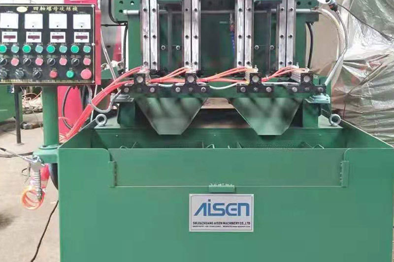
AISEN Four axis nut tapping machine ready for shipment to Russia
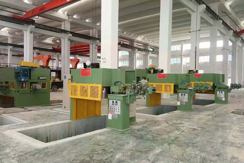
AISEN machinery inverted wire drawing machine
MESSAGES
We will contact you within one working day. Please pay attention to your email.
Qucik Link
Contact
Phone: +86-15100123091
E-mail: info@sjzaisen.com
Address: No.41 Zhaiying South Street, Yuhua District, Shijiazhuang City, Hebei Province China