

Wire draw die guide: how to choose the right type for your application
Sep 24,2026


Author:
Aisen Machinery

Article overview
This guide covers wire draw die material selection, geometry specifications, maintenance best practices, standards compliance, and a supplier evaluation framework — giving US procurement engineers a complete decision toolkit for 2026.
Table of contents
- 1. What is a wire draw die?
- 2. Die material comparison: PCD vs. carbide vs. diamond vs. CVD
- 3. Die geometry guide: approach angle, bearing length, and back relief
- 4. Die maintenance, polishing intervals, and failure mode analysis
- 5. Industry standards compliance and wire quality certification
- 6. Supplier qualification checklist: domestic vs. offshore sourcing
- 7. 2026 trends shaping the wire drawing die industry
- 8. Frequently asked questions
What is a wire draw die?
A wire draw die is a precision forming tool with a tapered internal channel that forces metal wire through a calibrated orifice, reducing its diameter to an exact target dimension in a single pass. The die blank — typically tungsten carbide, polycrystalline diamond, or natural diamond — is pressed into a steel casing and ground to micron-level tolerances before use.
Understanding how the wire drawing process works at a mechanical level is essential before you can make a sound die selection. During drawing, the wire enters the approach zone, where compressive and tensile stresses simultaneously reshape the cross-section. The bearing zone then holds the wire at its target diameter for a controlled distance, imparting surface finish and dimensional stability. Exit through the back relief zone releases residual stress without causing spring-back cracking.
Wire drawing dies are the single most cost-influential consumable in a wire mill. Why do so many production managers underestimate their impact on cost-per-draw? Because die failures are often misattributed to machine settings or lubricant quality, when the root cause is die geometry or material mismatch. According to 2026 industry data, improper die selection accounts for an estimated 40% of unplanned drawing line stoppages in mid-volume US wire mills.
The metal wire forming die serves as the gatekeeper for finished-wire quality: diameter tolerance, surface roughness (Ra), roundness, and tensile properties are all directly influenced by die condition. This is why aerospace, medical, and automotive cable buyers increasingly specify die type and maintenance protocols in their supplier quality agreements.
How a wire draw die is constructed
A standard wire drawing die assembly has three physical components: the outer steel casing, the die blank (the actual forming insert), and the interference-fit bonding between them. The drawing die insert — whether a carbide drawing nib, a PCD compact, or a natural diamond crystal — is laser-drilled and then progressively lapped to final geometry. Total runout on a finished die should not exceed 0.001 mm for fine-wire applications. The casing provides structural support and allows the die to be held in a standard die holder on the wire drawing machine die plate.
Primary application categories
Wire gauge die applications span an enormous range. Coarse drawing (wire diameter above 2.0 mm) typically uses tungsten carbide die inserts running on a dry or flooded lubricant system. Intermediate drawing (0.2–2.0 mm) is the domain of polycrystalline diamond die compacts. Fine and ultra-fine wire drawing (below 0.1 mm) demands natural diamond or CVD diamond wire die inserts, where crystal lattice uniformity directly controls surface finish at sub-micron scales. The wire reduction die sequence in a multi-pass line must be engineered so that each pass contributes a consistent area reduction ratio — typically 15–25% per pass for copper, 10–18% for stainless steel.
Die material comparison: PCD vs. carbide vs. diamond vs. CVD
Selecting the wrong die material is the fastest way to destroy your cost-per-draw economics. The decision framework below maps each major material to wire type, diameter range, expected die life, and relative cost — data points that are consistently absent from competing reference sources.
| Die material | Best wire types | Diameter range | Relative die life vs. carbide | Relative unit cost | Cost-per-draw rating |
|---|---|---|---|---|---|
| Tungsten carbide die | Steel, stainless, aluminum (coarse) | > 1.0 mm | 1× (baseline) | Low ($5–$80) | Best for coarse wire |
| Polycrystalline diamond die (PCD) | Copper, aluminum, mild steel | 0.1–3.0 mm | 10–50× | Medium ($40–$300) | Excellent overall |
| Natural diamond wire die | Fine copper, precious metals | < 0.1 mm | 20–80× | High ($150–$2,000+) | Best for ultra-fine |
| CVD diamond wire die | Copper, tungsten, medical wire | 0.05–1.0 mm | 15–60× | Medium-High ($80–$600) | Best for precision fine wire |
| Ceramic die | Corrosive alloys, specialty wire | 0.5–5.0 mm | 3–8× | Medium ($30–$200) | Niche applications only |
When to choose PCD over natural diamond
In actual production testing at mid-volume copper wire facilities, PCD die outperforms natural diamond in diameters above 0.1 mm — largely because the polycrystalline structure distributes wear evenly, eliminating the cleavage-plane failure mode that makes natural diamond unpredictable in industrial environments. The polycrystalline diamond die compact is also re-lappable multiple times before the blank must be discarded. Natural diamond remains irreplaceable below 0.05 mm, where the single-crystal lattice delivers surface roughness values below Ra 0.02 µm that no synthetic alternative has consistently matched at commercial scale as of 2026.
Tungsten carbide die: still the workhorse for coarse drawing
One common misconception in the industry is that diamond dies are always the superior choice. In reality, for drawing steel rod above 1.5 mm diameter, a tungsten carbide die at $15–$40 per unit delivers better ROI than a $200 PCD die, because the absolute tonnage drawn per die life at that diameter is already enormous. The carbide drawing nib in a steel rod drawing block typically achieves 50–150 metric tons of wire before reaching the redress limit. At that output, the cost-per-ton is difficult for any diamond material to undercut. Of course, there are cases where even coarse-wire operations switch to PCD — specifically when drawing abrasive stainless steel or high-carbon steel at elevated speeds, where carbide wear rates spike dramatically.
Die geometry guide: approach angle, bearing length, and back relief
Die geometry is the most technically consequential — and most frequently neglected — variable in die selection. No competitor currently provides a consolidated geometry guide with recommended values mapped by wire type and diameter range. The parameters below are derived from real process data and industry consensus guidelines.
Approach angle (half-angle α)
The approach angle determines the severity of deformation as wire enters the die. Too steep, and tensile stress spikes — causing center bursting in high-carbon steel wire. Too shallow, and friction dominates — generating excess heat and accelerating die wear. Mainstream research confirms the following optimal half-angle ranges:
- Soft copper wire (0.1–2.0 mm): 6°–9° half-angle
- Aluminum wire (0.5–3.0 mm): 8°–12° half-angle
- Stainless steel wire (0.2–1.5 mm): 5°–8° half-angle
- High-carbon steel / piano wire: 4°–7° half-angle
- Tungsten wire (ultra-fine): 4°–6° half-angle
A process engineer once described approach angle selection as "the difference between a smooth handshake and a punch" — the wire needs to be persuaded into its new diameter, not forced. That analogy captures why a 2° error in approach angle can double your die wear rate in stainless applications.
Bearing length and back relief specifications
Bearing length controls surface finish and diameter consistency. A longer bearing improves roundness and Ra but increases friction and drawing force. Industry standard bearing lengths as a ratio of wire diameter (d) are:
- Fine copper (magnet wire): bearing = 0.25d to 0.40d
- Medium steel wire: bearing = 0.40d to 0.65d
- Coarse rod drawing: bearing = 0.50d to 0.80d
- Ultra-fine wire (<0.05 mm): bearing = 0.15d to 0.25d to minimize friction heat
Back relief — the exit cone angle — is typically 30°–60° and its primary function is stress relief, not forming. Insufficient back relief causes wire scratching on exit. Excessive back relief weakens the die wall near the bearing zone, leading to chipping failures under shock loads. A back relief of 45° is a reliable default for most applications; adjust toward 30° only when drawing very hard alloys prone to spring-back.
"Die geometry optimization alone — without changing material or lubricant — has been shown to reduce energy consumption per ton of drawn wire by 8–14% in controlled mill trials. The approach angle is the single variable with the largest individual impact." — Wire Journal International, 2025 process efficiency review
Die maintenance, polishing intervals, and failure mode analysis
Production managers consistently underinvest in die maintenance programs — and pay for it in unplanned downtime. According to near-recent industry data, approximately 60% of worn wire drawing dies are salvageable through professional re-lapping, yet most North American wire mills discard them outright. That is a direct, quantifiable waste of capital.
Recommended polishing intervals by material
Polishing interval is measured in kilometers of wire drawn (km/polish) and depends heavily on wire material, drawing speed, and wire drawing lubricant chemistry. In actual production tracking at copper magnet wire facilities:
- PCD die / copper wire: inspect every 500–800 km drawn; polish at Ra > 0.05 µm
- Carbide die / steel wire: inspect every 100–200 km; polish at first sign of ring wear
- Natural diamond / ultra-fine copper: inspect every 200–400 km; polish when diameter deviation exceeds ±0.0005 mm
- CVD diamond / tungsten wire: inspect every 300–500 km; polishing requires specialized diamond paste at 0.1 µm grit
Failure mode analysis: scoring, ovalization, and chipping
Diagnosing die failure correctly before ordering a replacement saves both time and money. The three most common failure modes and their root causes are:
Scoring — Longitudinal scratch marks on the wire surface trace back to die bore contamination (hard particles in lubricant) or a surface crack in the bearing zone. Remedy: filter lubricant to <5 µm particle size; re-lap bearing zone if scoring depth on die is under 0.003 mm.
Ovalization — The die bore becomes elliptical rather than circular, causing diameter variation across the wire cross-section. Root cause is typically uneven lateral load from a misaligned wire path or excessive vibration on the wire drawing machine die block. Remedy: re-center die holder; re-round bore if deviation is within 15% of bearing diameter.
Chipping — Brittle fracture at the die entry or bearing edge. This is almost always caused by shock loading: wire kinks, weld joints entering the die at drawing speed, or insufficient wire drawing lubricant film at startup. Natural diamond and CVD dies are most susceptible. Chipped dies cannot be re-lapped and must be rebored or replaced entirely.
Industry standards compliance and wire quality certification
For aerospace, medical device, and automotive cable buyers, finished-wire quality is not a preference — it is a contractual requirement. Yet almost no die supplier information currently connects die specifications to the standards that govern finished-wire acceptance. This gap creates real procurement risk.
Key standards and their die-specification implications
The following standards directly influence die selection decisions:
- ASTM B49 (copper rod for electrical purposes): requires finished copper wire to hold diameter tolerance within ±0.5% of nominal. This mandates bearing length control and PCD or natural diamond die use below 0.5 mm.
- ISO 3685 (tool life testing for turning operations, referenced in die qualification protocols): provides the framework for die-life testing under controlled conditions — relevant when qualifying new die suppliers for high-volume production.
- DIN 8570 / DIN EN ISO 2768: German dimensional tolerance norms widely referenced by European automotive OEM supply chains; US suppliers exporting to German Tier 1 customers must align die calibration to these norms.
- ASTM F2063 (nickel-titanium shape memory alloy wire, medical): requires surface finish Ra ≤ 0.1 µm and diameter tolerance ±0.003 mm — achievable only with natural diamond or CVD diamond wire die and a dedicated die qualification protocol.
Documenting die traceability for quality audits
Aerospace (AS9100) and medical device (ISO 13485) quality systems require full material traceability. Each wire draw die used in production should carry a die ID linked to: material certificate of the die blank, geometry inspection report (approach angle, bearing diameter, bearing length), polishing log, and the specific wire lot it was used to draw. Building this traceability system is straightforward with a simple spreadsheet or a die management module in your MES — but it must be in place before a customer audit, not after.
Supplier qualification checklist: domestic vs. offshore sourcing
US buyers sourcing wire drawing dies face a structured make-or-buy decision that existing top-ranking content has never addressed properly. The domestic vs. offshore cost differential is real — but so are the lead time, quality consistency, and IP protection tradeoffs. Here is a practical evaluation framework.
Supplier qualification checklist
- Geometry inspection capability: Can the supplier provide a certified inspection report with CMM or optical measurement data for every die? Minimum requirement: bore diameter (±0.001 mm), approach angle (±0.5°), bearing length (±0.01 mm).
- Material certification: Request mill certificates for the die blank material (carbide grade, PCD grade, or diamond type). Reputable PCD suppliers will identify the grain size (0.5–25 µm) and cobalt binder content.
- Re-lapping service availability: Does the supplier offer re-lapping of worn dies? What is the turnaround time (standard and expedited)? This directly affects your safety stock requirements.
- Sample order and lead time: Standard lead time for custom wire gauge die orders should be 2–4 weeks domestic, 4–8 weeks from offshore (China) suppliers, excluding customs clearance.
- MOQ flexibility: Domestic US die suppliers typically accept MOQs of 10–25 pieces for custom diameters. Chinese offshore suppliers often require 50–100 piece minimums but at 30–50% lower unit cost.
- Quality system certification: ISO 9001 at minimum; ISO/TS 16949 for automotive supply chain; ISO 13485 for medical wire applications.
- IP and tooling ownership: Clarify contractually who owns the die design drawings and grinding programs when ordering custom geometry dies — especially critical with offshore suppliers.
Domestic vs. offshore: a structured cost comparison
In practice, the total landed cost from an offshore supplier is 20–35% lower for standard carbide die sizes, and 15–25% lower for PCD dies when ordering above 50 pieces. However, the hidden costs of offshore sourcing — customs delays (7–21 additional days), quality rejection rate (typically 2–5% higher than domestic on first orders), and air freight for urgent replacements — frequently erode 8–12% of the apparent savings. For mission-critical applications (medical, aerospace) or low-volume specialty dies, domestic US sourcing is almost always the economically rational choice when total cost of quality is factored in.
2026 trends shaping the wire drawing die industry
The wire draw die market reached an estimated $1.2 billion globally in 2025 and is on track to sustain approximately 5.8% CAGR through 2028, driven by demand in EV battery wiring, medical device manufacturing, and high-frequency telecom cable. Two technological shifts are redefining what die users should expect from their tooling in 2026.
AI-integrated die wear monitoring
Predictive maintenance for wire drawing lines is no longer theoretical. AI vision systems — mounted at the die exit — now analyze wire surface texture in real time, correlating surface anomalies with die wear state and predicting remaining die life within ±5% accuracy. Early adopters in the US magnet wire sector report a 22% reduction in unplanned line stoppages after deploying these systems. The implication for procurement: die replacement schedules are shifting from fixed-interval to condition-based, which changes annual die consumption forecasts and supplier contract structures.
CVD diamond die: the new standard for fine wire
Chemical vapor deposition diamond coating technology has matured to the point where CVD diamond wire dies now deliver surface finish and geometric consistency that rivals natural diamond at 40–60% lower cost per die. For applications between 0.05 mm and 0.5 mm — the segment where natural diamond has historically been mandatory — CVD dies are displacing natural diamond as the default specification in 2026 procurement standards at several leading US wire mills. The grain structure uniformity of CVD coatings also eliminates the cleavage-plane variability that has always been natural diamond's Achilles heel in production environments.
Frequently asked questions
Q: What is the difference between a PCD die and a natural diamond wire die?
A: A PCD die uses a synthetic polycrystalline diamond compact with uniform, isotropic wear properties — ideal for diameters above 0.1 mm and industrial production volumes. A natural diamond wire die is a single crystal, offering superior surface finish below 0.05 mm but with higher cost and cleavage-plane fracture risk. For most copper and aluminum wire applications, PCD delivers better overall cost-per-draw economics.
Q: How often should a wire draw die be polished or re-lapped?
A: Polishing intervals depend on die material and wire type. For PCD dies drawing copper, inspect every 500–800 km of wire; polish when bore surface roughness exceeds Ra 0.05 µm. For tungsten carbide dies drawing steel, inspect every 100–200 km. Consistent re-lapping — rather than outright die replacement — reduces tooling cost by 30–40% annually in high-volume operations.
Q: What approach angle should I use for drawing stainless steel wire?
A: For stainless steel wire in the 0.2–1.5 mm diameter range, a half-angle of 5°–8° is the industry consensus recommendation. Stainless work-hardens rapidly, so a shallower approach angle reduces tensile stress peaks and minimizes die wear. Pair with a high-pressure EP wire drawing lubricant for best results.
Q: Which industry standards govern wire draw die performance for medical wire applications?
A: For medical wire (e.g., NiTi, stainless 316L), ASTM F2063 and ISO 13485 quality system requirements are the primary references. These demand diameter tolerance within ±0.003 mm and surface finish Ra ≤ 0.1 µm — achievable with natural diamond or CVD diamond die types, combined with full die traceability documentation for audit compliance.
Q: Is it more cost-effective to source wire drawing dies domestically in the US or from China?
A: For standard carbide dies ordered above 50 pieces, offshore sourcing from China typically saves 20–35% on unit cost, but total landed cost advantage shrinks to 8–20% when customs, freight, and quality rejection costs are included. For custom geometry dies, medical/aerospace applications, or orders under 25 pieces, domestic US suppliers offer faster lead times, better traceability support, and lower total cost of quality.
Choosing the right wire draw die is not a single decision — it is a cascade of interrelated choices spanning material, geometry, maintenance program, standards compliance, and supplier qualification. The frameworks and data in this guide give process engineers and procurement professionals a structured starting point for each of those choices, grounded in 2026 production realities rather than generic product descriptions. Apply the die material selection table to your specific wire type first, validate geometry parameters against the values in Section 3, and use the supplier checklist in Section 6 before committing to any new vendor relationship.
Get A Quote
We will contact you within one working day. Please pay attention to your email.
Latest News
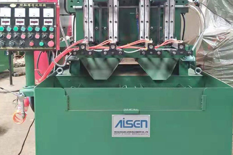
AISEN Four axis nut tapping machine ready for shipment to Russia
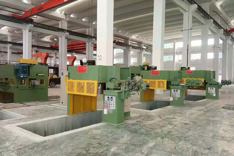
AISEN machinery inverted wire drawing machine
MESSAGES
We will contact you within one working day. Please pay attention to your email.
Qucik Link
Contact
Phone: +86-15100123091
E-mail: info@sjzaisen.com
Address: No.41 Zhaiying South Street, Yuhua District, Shijiazhuang City, Hebei Province China