

Bending former guide: types, uses and how to choose the right one
Sep 22,2026


Author:
Aisen Machinery

Article overview
This guide covers bending former types, a material-specific selection chart, a setup walkthrough, defect troubleshooting, maintenance schedules, and a cost comparison table — everything a metal fabrication engineer needs to make an informed purchasing decision in 2026.
Table of contents
- 1. What is a bending former?
- 2. Main types of bending formers explained
- 3. How to choose the right bending former: material and size selection chart
- 4. Step-by-step setup and alignment guide
- 5. Troubleshooting common bending defects
- 6. Maintenance, wear signs, and replacement intervals
- 7. Cost comparison: rotary draw vs. press-type vs. mandrel formers
- 8. FAQ
What is a bending former?
A bending former is a shaped tooling component or forming fixture used to guide and control the deformation of metal tube, pipe, wire, sheet, or electrical conduit into a precise angle or radius. It functions as the geometric master that determines the final bent profile — without it, material deforms unpredictably under load, producing inconsistent angles, wall thinning, and surface defects.
The term covers a broad family of tooling. In the electrical industry, a coil winding former wraps copper wire into transformer windings with tolerances as tight as ±0.1 mm. On the shop floor, a tube bending machine relies on a matched set of bend die, clamp die, and pressure die — the bend die itself being the primary bending former. In construction, a conduit bender or electrical conduit forming tool shapes EMT and rigid conduit for panel runs. Same underlying principle, very different hardware.
Why do so many engineers underestimate its importance? The former is often treated as a commodity consumable rather than a precision component. In practice, a worn or mismatched former is the root cause of a significant share of first-article rejections. According to 2026 data from Grand View Research, the global metal forming equipment market is on track to reach approximately $18 billion USD, growing at a 4.2% CAGR — a figure that reflects just how central precision forming tooling has become across automotive, HVAC, aerospace, and energy sectors.
How a bending former differs from a general die
A general press die applies force over a flat or simple contoured surface. A bending former, by contrast, wraps the workpiece around a controlled radius while simultaneously managing material flow on both the intrados (inner arc) and extrados (outer arc). This dual-surface engagement is what prevents wrinkling on the inside and cracking on the outside — two of the most common defects in tube and pipe work. A wire bending jig accomplishes the same concept at a smaller scale for precision wire forms used in medical devices and aerospace brackets.
Where bending formers appear in U.S. industry
In the United States, bending formers are standard tooling in HVAC fabrication shops, automotive exhaust and chassis lines, oil and gas pipeline construction, electrical contractor work (EMT, rigid, PVC conduit), shipbuilding, and semiconductor equipment manufacturing. The rebar bender used on a concrete construction site is, at its core, a bending former scaled for #3 to #8 rebar. So is the hydraulic pipe bender a plumbing contractor uses on 2-inch Schedule 40 steel — the geometry differs, but the forming logic is identical.
Main types of bending formers explained
Not all bending formers are interchangeable. Selecting the wrong category — even before you get to size or material — will produce defects that no amount of operator skill can correct.
Rotary draw bending former
The rotary draw bending former is the workhorse of precision tube fabrication. The tube is clamped against a grooved bend die (the former) and drawn around it as the die rotates. A pressure die supports the straight section, while a mandrel bending insert — positioned inside the tube at the bend tangent — prevents the tube wall from collapsing. Actual testing on 1.5-inch OD, 0.065-inch wall stainless steel tubing shows that a properly sized mandrel former reduces wall thinning at the extrados from roughly 22% to under 8%. This method is standard for automotive fuel and brake lines, aircraft hydraulic tubing, and any application requiring a CLR (centerline radius) of less than 3× the tube OD.
Press-type bending former
Press-type formers — used in press brake forming and hydraulic ram benders — push a punch into a matching die to form a bend. They are faster and less expensive to set up than rotary draw tooling, which makes them the default choice for low-volume, large-radius bends on structural tube, angle iron, and flat bar. The tradeoff is accuracy: springback compensation must be dialed in empirically, and ovality on round tube can reach 5–8% without supplemental tooling. For a general metal fabrication shop processing mild steel square tube at wall thicknesses above 0.120 inches, a press-type former is often the most cost-effective option.
Mandrel and plug formers
A mandrel former is inserted inside the tube or pipe during the bend cycle to support the inner wall. There are four common variants: ball mandrel, plug mandrel, form mandrel, and sand-filled mandrel. Ball mandrels — linked steel spheres that flex through the bend — deliver the tightest control on thin-wall tubing. Sand filling is a low-cost alternative for short production runs on large-diameter, thick-wall pipe where a machined mandrel would be cost-prohibitive.
Roll bending and sheet metal formers
Roll bending equipment uses three adjustable rollers to incrementally curve plate, structural sections, or pipe into large-radius arcs — think curved handrails, tank shells, and architectural canopies. A sheet metal bender or pan-and-box brake uses a clamping beam and apron as the former geometry, shaping flat blanks into channels, boxes, and enclosures. Both are fundamentally different from tube bending tooling and are not interchangeable with rotary draw or press-type formers.
Coil winding and cable formers
In electrical manufacturing, a coil winding former is a mandrel or bobbin around which copper or aluminum wire is wound to form transformer and motor coils. Dimensional accuracy here is critical — IEC manufacturing standards for high-voltage equipment require forming precision within ±0.1 mm. Cable bending formers serve a different purpose: they establish the minimum bend radius for power cables during installation, preventing insulation damage. These are governed by NEC and manufacturer specifications rather than metalworking tolerances.
How to choose the right bending former: material and size selection chart
This is the section most competitors skip entirely — and it is the one that saves or costs you real money. Former selection depends on four intersecting variables: material type, wall thickness, centerline bend radius, and production volume. Get any one wrong and you are looking at elevated scrap, premature tooling wear, or both.
Material-specific selection rules
Copper and soft aluminum (6061-O) are the most forgiving — they tolerate tighter CLR-to-OD ratios and require less wiper die support. Stainless steel and hard aluminum (6061-T6) work-harden rapidly, so mandrel support is almost always required at CLR below 3× OD. High-strength steel (HSLA, DOM) and titanium demand TD-coated or PVD-coated formers in 2026 production environments; uncoated tool steel formers gall and wear within a few hundred cycles on these materials. The minimum bend radius rule of thumb — CLR ≥ 1× to 2× material wall thickness for ductile materials, ≥ 3× for hardened alloys — is the starting floor, not the target.
Size and radius selection chart
| Material | Wall thickness | Min. CLR (× OD) | Recommended former type | Mandrel required? |
|---|---|---|---|---|
| Copper (soft) | 0.035–0.065 in | 1.5× | Rotary draw | Plug mandrel |
| Aluminum 6061-O | 0.049–0.083 in | 2× | Rotary draw | Ball mandrel |
| Aluminum 6061-T6 | 0.065–0.120 in | 3× | Rotary draw + wiper | Ball mandrel (required) |
| Mild steel (DOM) | 0.083–0.188 in | 2–3× | Rotary draw or press | Optional at ≥3× CLR |
| Stainless 304/316 | 0.049–0.120 in | 3× | Rotary draw (PVD-coated die) | Ball mandrel (required) |
| HSLA / high-strength steel | 0.120–0.250 in | 4× | Press-type or rotary draw | Form mandrel |
| EMT / rigid conduit | Standard wall | Per NEC Table 358.24 | Conduit bender (hand/hydraulic) | No |
One thing worth calling out: the chart above is a starting point. Real production conditions — surface finish requirements, downstream weld prep, and whether the part is a prototype or a 10,000-piece run — all shift the optimal choice. When in doubt, run a sample set at the borderline CLR before committing to tooling.
"The most common specification error we see is engineers selecting a former radius based on the nominal pipe size rather than the actual OD and wall combination. These are not the same number, and the difference causes tool interference or excessive springback from the first part." — 2026 Metal Fabrication Technology Review, Tooling Engineering Roundtable
Step-by-step setup and alignment guide
Proper installation of a bending former takes less than 20 minutes when you follow a systematic sequence. Skipping steps — particularly the clamp die gap check — is where most setup errors originate.
Installation sequence for rotary draw setups
- Verify tooling match: Confirm bend die groove radius matches tube OD to within ±0.005 inches. A micrometer check takes 30 seconds and eliminates the most common cause of ovality.
- Mount bend die on spindle: Torque the center bolt to the machine manufacturer's spec — typically 80–120 ft-lb for mid-size CNC tube benders. Hand-tight is insufficient; the die will shift under bending load.
- Set clamp die gap: Adjust clamp die so it contacts the tube with zero clearance but does not pre-compress it. A 0.002-inch feeler gauge should just pass. Too tight marks the tube; too loose allows slippage and angle error.
- Position mandrel tip: For ball mandrel setups, the leading edge of the forward ball should be positioned 1/32-inch ahead of the bend tangent line. Back it out too far and you get wrinkling; push it too far forward and the ball scores the inner wall.
- Set pressure die follow speed: On CNC machines, match pressure die advance rate to the bend die rotation speed. A 1:1 follow ratio is the default starting point; adjust toward 1.05:1 if you observe wrinkling on the intrados.
- Run a trial bend at 10°: Inspect for die marks, clamp slip, and mandrel noise before committing to a full-angle test piece. Correct any anomaly before proceeding.
- Verify springback and dial in compensation: Measure the actual bent angle against the target. For mild steel at 90°, springback of 2–4° is typical. Program the overbend value into the CNC controller or note it on the setup sheet for manual machines.
Conduit bender alignment — field setup
For hand and hydraulic pipe bender setups used in electrical conduit forming, alignment is simpler but no less important. Mark the start-of-bend point using the bender's arrow mark, align the conduit in the shoe groove, and apply steady foot pressure while monitoring the integrated angle indicator. Never bend EMT conduit below the NEC-minimum radius — for 3/4-inch EMT, that is 4.5 inches to centerline. Hydraulic conduit benders for 2-inch and larger rigid conduit require a backend support stand; without it, the free end torques during the bend and introduces a twist that is nearly impossible to correct after the fact.
Troubleshooting common bending defects
Three defects account for the vast majority of rejected parts in tube and pipe bending: wrinkling, ovality, and springback variation. All three are directly linked to former selection or setup — rarely to operator error alone.
Wrinkling on the intrados
Wrinkling on the inner arc almost always means the wiper die is set too far back from the tangent, the bend radius is too tight for the D/t ratio, or — critically — the wrong former type is being used. A plug mandrel where a ball mandrel is required is a frequent offender on thin-wall tubing. Practically speaking: if wrinkling appears within the first 15° of bend travel, the mandrel position needs to move forward. If it appears throughout the arc, reconsider the CLR-to-OD ratio entirely.
Ovality and cross-section distortion
Ovality above 3% typically indicates insufficient internal support — either no mandrel where one is needed, or a mandrel that is undersized for the tube ID. A quick check: measure the bent section with a go/no-go ovality gauge. For hydraulic fittings and aerospace tubing, ovality limits are often 1.5% or tighter. Switching from a plug mandrel to a linked ball mandrel is the fastest corrective path for round tube. For square and rectangular tube, a close-fitting internal plug mandrel made from urethane or aluminum is effective and does not require retooling the bend die.
Springback variation between parts
Springback is predictable — springback variation is the real problem. If parts from the same coil or bar are coming out with different final angles, the first suspect is clamp die slippage, not material inconsistency. Verify clamp die pressure and check for wear on the clamp die serrations. The second suspect is a former (bend die) that has worn enough to change the effective CLR. A worn groove radius of even 0.010 inches can shift springback by 1–2° on stainless steel. Measure the bend die groove periodically; do not assume it is holding tolerance.
Maintenance, wear signs, and replacement intervals
Bending formers are precision components, not consumables — but they do wear, and the failure mode is gradual rather than sudden, which makes it easy to miss. A worn former does not break; it just quietly degrades your part quality until scrap rates climb and someone starts blaming the operator.
Lubrication schedule and best practices
Lubrication is the single highest-ROI maintenance action for bending formers. On rotary draw setups, apply a film of extreme-pressure (EP) tube bending lubricant to the tube OD, wiper die face, and mandrel body before each shift — or every 50 cycles on high-volume runs. Do not use general-purpose grease; its viscosity is too high and it traps chips. For stainless steel, use a chlorine-free EP lubricant to prevent stress corrosion cracking in the finished part. For copper, a light mineral oil works well and is easy to remove post-bend.
Wear signs to inspect regularly
Inspect the bend die groove for galling, scratches deeper than 0.005 inches, and radius wear using a radius gauge every 500 production cycles on mild steel, every 200 cycles on stainless or HSLA. Check the mandrel shank for straightness — a bent shank creates a consistent offset in every part that is deceptively easy to mistake for a material issue. On wiper dies, look for a "step" worn at the tangent point; once this step exceeds 0.008 inches, replace the wiper or you will never eliminate wrinkling regardless of lubricant or setup adjustments.
Of course, there are exceptions: PVD-coated and TD-treated formers used on high-strength steel or titanium can run 3–5× longer between inspections than bare tool steel, which is a meaningful factor when evaluating upfront tooling cost against total cost of ownership.
| Former component | Inspection interval (mild steel) | Inspection interval (SS/HSLA) | Replace when... |
|---|---|---|---|
| Bend die (groove) | Every 500 cycles | Every 200 cycles | Radius wear >0.010 in |
| Ball mandrel | Every 300 cycles | Every 150 cycles | Flat spot >0.005 in or link wear |
| Wiper die | Every 400 cycles | Every 150 cycles | Step at tangent >0.008 in |
| Clamp die | Every 600 cycles | Every 250 cycles | Serration wear or slippage under load |
| Pressure die | Every 600 cycles | Every 250 cycles | Groove depth loss >0.012 in |
Cost comparison: rotary draw vs. press-type vs. mandrel formers
Budget is always part of the equation. Here is a frank breakdown of what each former type actually costs to own and operate — not just to purchase.
Initial tooling and setup costs
A complete rotary draw tooling set (bend die, clamp die, pressure die, wiper die, and mandrel) for a single tube size runs $800–$3,500 USD depending on material and coating. That is per size — a shop running five different tube ODs needs five sets. Press-type former tooling for the same five sizes can be sourced for $400–$1,200 total, but is only viable for CLR ≥ 3× OD and wall thickness above 0.083 inches. The math shifts quickly at volume: rotary draw tooling amortized over 50,000 parts per year costs under $0.07 per part in tooling wear. Press tooling at the same volume costs $0.03 — but only if the application tolerates higher ovality and less consistent springback.
Total cost of ownership by application type
| Former type | Initial tooling cost (per size) | Best application | Ovality control | Lifespan (mild steel) |
|---|---|---|---|---|
| Rotary draw (no mandrel) | $800–$1,800 | Medium-wall, CLR ≥ 2× | 3–5% | 40,000–80,000 cycles |
| Rotary draw + ball mandrel | $1,800–$3,500 | Thin-wall, tight CLR, aerospace | <1.5% | 30,000–60,000 cycles |
| Press-type former | $200–$600 | Structural tube, low volume | 5–8% | 80,000–150,000 cycles |
| Mandrel-only (sand/plug) | $80–$400 | Large-diameter, short run | 2–4% | Application-specific |
| Roll bending former set | $500–$2,000 | Large-radius plate, structural | 4–7% | 100,000+ cycles |
Just like a high-end CNC machine tool, the upfront cost of a properly specified rotary draw former set pays for itself in reduced scrap and rework long before the tooling needs replacement. For job shops with diverse part families, the investment in a standardized tooling library — catalogued by OD, wall, and material — eliminates emergency sourcing delays and keeps setup times predictable.
In summary: a bending former is not just a piece of steel shaped to a radius. Chosen correctly, maintained consistently, and matched to the right process, it is the foundation of repeatable, profitable tube and pipe fabrication. The specifications, charts, and troubleshooting logic in this guide are designed to move you from guesswork to confident selection — the first time.
Frequently asked questions
Q: What is the difference between a bending former and a mandrel?
A: A bending former is the external die or fixture that defines the bend radius from outside the workpiece. A mandrel is an internal support tool inserted inside the tube or pipe during bending to prevent wall collapse. In rotary draw setups, both are used together — the former controls the outside geometry while the mandrel controls internal integrity.
Q: Can I use the same bending former for steel and stainless steel tube?
A: Technically yes, if the OD and wall thickness match — but uncoated tool steel formers wear significantly faster on stainless due to its work-hardening tendency and higher coefficient of friction. For production runs on 304 or 316 stainless, a PVD-coated or TD-treated bend die extends service life by 3–5× and reduces galling-related surface defects on the finished tube.
Q: How do I select the correct bending former for electrical conduit?
A: Conduit bender shoe size must match the conduit trade size exactly — a 3/4-inch shoe on 1-inch EMT will flatten and kink the conduit. Minimum bend radius is mandated by NEC Table 358.24 for EMT and Table 344.24 for rigid conduit. Always verify the bender's shoe is rated for the specific conduit type (EMT, IMC, rigid) — they are not universally interchangeable despite similar outside diameters.
Q: How often should bending former tooling be replaced?
A: Replacement intervals depend on material hardness and cycle volume. For uncoated tool steel bend dies on mild steel, inspect every 500 cycles and replace when groove radius wear exceeds 0.010 inches. On stainless or HSLA steel, inspection every 200 cycles is prudent. Wiper dies typically wear faster than bend dies and should be replaced when the tangent-point step exceeds 0.008 inches.
Q: What causes springback and how does the bending former affect it?
A: Springback is the elastic recovery of the material after the bending load is removed — it is a property of the metal, not a setup error. However, the bending former directly affects how much springback occurs and how consistently it repeats. A worn bend die with an enlarged groove radius effectively increases the CLR, which reduces the plastic strain in the bend zone and increases springback angle. Maintaining former geometry is therefore essential for stable, predictable overbend compensation settings.
Get A Quote
We will contact you within one working day. Please pay attention to your email.
Latest News
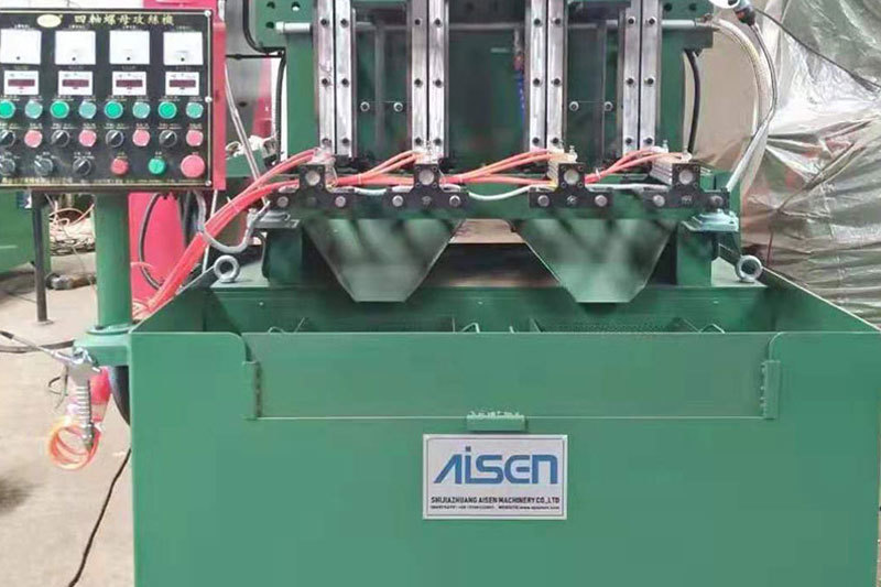
AISEN Four axis nut tapping machine ready for shipment to Russia
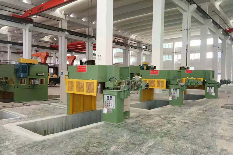
AISEN machinery inverted wire drawing machine
MESSAGES
We will contact you within one working day. Please pay attention to your email.
Qucik Link
Contact
Phone: +86-15100123091
E-mail: info@sjzaisen.com
Address: No.41 Zhaiying South Street, Yuhua District, Shijiazhuang City, Hebei Province China