

Cold heading process with multiple headers: stages, dies and material flow
Nov 12,2026


Author:
Aisen Machinery

Article overview
This guide explains how a Multiple Header Cold Heading Machine transforms wire rod into precision fastener blanks through sequential die stations — covering stages, die geometry, material flow, and quality control.
Table of contents
- 1. What is a multiple header cold heading machine?
- 2. Wire feeding, blank cutting and initial heading
- 3. Die stations: sequence, geometry and function
- 4. Material flow and metal deformation mechanics
- 5. Process parameters and quality control
- 6. Equipment selection and tooling considerations
- 7. Common defects, troubleshooting and process limits
- 8. FAQ
What is a multiple header cold heading machine?
A Multiple Header Cold Heading Machine is a progressive cold forging press that forms metal wire into fastener blanks through two or more sequential die stations — without heating the material — achieving precise geometry and high tensile strength in a single automated cycle.
Unlike a single-blow header, which completes the forming operation in one stroke, a multi-station cold forming machine distributes the total deformation across several punches and dies. Each station handles a fraction of the displacement, keeping strain within the material's work-hardening tolerance. The result is a net-shape or near-net-shape blank that requires minimal downstream machining.
Why do so many fastener plants rely on this approach rather than hot forging or machining? The answer comes down to material efficiency, cycle speed, and mechanical property outcomes. Cold-worked steel develops a refined grain structure that improves fatigue resistance — a critical attribute for automotive and structural fasteners. High-speed header machines operating at 100–400 parts per minute make the economics compelling at scale.
In the Argentine fastener manufacturing sector, demand for progressive cold forging machines has grown alongside local automotive assembly and construction supply chains. Equipment capable of producing M6–M24 bolt blanks at throughput rates above 150 ppm is now considered baseline for competitive production.
Core process distinction: single-blow vs. multi-blow headers
A single-blow header forms the head in one punch stroke, limiting geometry complexity and the volume of metal that can be displaced without cracking. A multi-blow or multi-station machine redistributes that displacement. For example, forming a hex flange bolt head from 10 mm wire may require three to four stations: one to pre-upset the shank end, one to form the rough head volume, one to coin the flange profile, and a final station to trim or extrude the shank. Each station operates within roughly 20–30% true strain per pass — well within the ductility limits of low-carbon and medium-carbon steel wire.
Application range and part families
Multi-station cold forming machines produce a wide range of parts beyond standard hex bolts: socket head cap screws, flange nuts, shoulder bolts, special pins, and cold-extruded shafts. The same machine platform — sometimes called an automatic parts former — can be retooled for different part families by changing the die cassettes and punch holders. This flexibility makes the investment attractive for contract manufacturers who serve multiple industries simultaneously.
Wire feeding, blank cutting and initial heading
Every cold heading cycle begins before the first die ever contacts metal. Consistent wire feed and accurate blank cutting are the foundation of dimensional stability downstream — problems introduced here cascade through every subsequent station.
Wire preparation and feed system
Wire rod arrives coiled and passes through a straightening unit — typically a series of offset rollers in two perpendicular planes — before entering the feed mechanism. Straightness tolerance after the unit should be within 0.5 mm per meter for diameters under 12 mm; deviations above this increase blank length scatter. The wire forming machine's servo or cam-driven feed rolls advance a precise length of wire on each cycle. Feed length directly determines blank volume, so roll wear and grip pressure must be monitored regularly. In practice, feed length variation of ±0.1 mm is achievable on well-maintained equipment, translating to blank weight variation below 0.3%.
Blank cutting: the shear-cut mechanism
The wire is sheared by a hardened carbide cutter against a stationary die bushing. This is not a clean orthogonal cut — the shear face exhibits a characteristic geometry: a rollover zone, a burnish band, a fracture zone, and a burr. For multi-station heading, the blank end quality matters because it contacts the first punch face directly. Excessive burr height (above 0.08 mm for M8 blanks) can cause off-center loading in station 1, initiating asymmetric upset.
The cut-to-heading transfer — where the blank is transferred from the cutter to the first die — is a critical motion sequence. On a blank cutting and heading machine, this transfer uses a finger-type or rotary transfer mechanism synchronized with the main crankshaft. Any timing deviation beyond ±1° of crankshaft angle typically produces misloaded blanks. Experienced operators know to watch for the characteristic "double-hit" sound that indicates a blank has been partially formed at the wrong angular position.
Die stations: sequence, geometry and function
The die station sequence defines the entire forming strategy. Each station must accomplish a specific deformation task while leaving the blank in a geometry that the next station can receive cleanly.
Typical station sequence for a hex bolt blank
- Station 1 — Point forming / shank chamfer: The punch forms a conical or flat chamfer on the shank end, improving thread rolling lead-in and removing the shear-cut burr geometry. Die cavity is a simple through-bore; forming is primarily on the punch face.
- Station 2 — Pre-upset (gather): A short, controlled upset expands the head-end diameter. The die confines the shank while the punch drives the free end into an open or semi-confined cavity. True strain at this station: approximately 0.25–0.35.
- Station 3 — Head forming: The pre-upset volume is driven into the hex or flange cavity. Full confinement on all sides. This station generates the highest forming force in the sequence — often 60–75% of total machine tonnage capacity.
- Station 4 — Coining / sizing: Final dimensional correction. Low displacement, high pressure. Establishes head height, bearing face flatness, and hex across-flats tolerance. Some machines include a simultaneous shank extrusion at this station.
- Station 5 (optional) — Trimming or secondary extrusion: On five-die machines, a trimming punch removes flash from the head periphery, or a forward extrusion reduces shank diameter for a reduced-shank bolt.
Die cavity geometry and tolerances
Cold heading dies and tools are precision components ground to tolerances of ±0.005 mm on critical features. Carbide inserts are the industry standard for bore and cavity surfaces, with TiN or TiCN coatings applied to punch faces to reduce adhesive wear. Die entry angles — the chamfer at the mouth of the cavity — typically range from 10° to 15° for steel; too shallow an angle increases surface pressure and galling risk, too steep reduces confinement and allows elastic springback to open dimensional tolerances.
"In cold forging, the die is not merely a shape — it is a stress field. Every radius, every angle, every surface finish contributes to how metal flows. A poorly designed die sequence doesn't fail catastrophically; it fails gradually, through dimensional drift and shortened tool life." — Industry consensus among cold forging process engineers, reflected across multiple technical handbooks on metal forming technology.
Material flow and metal deformation mechanics
Understanding material flow is what separates competent die designers from exceptional ones. Metal does not compress — it flows. Every cubic millimeter displaced by a punch must go somewhere, and predicting where is the core challenge of cold heading die design.
Flow patterns in confined and semi-confined cavities
In a fully confined cavity (closed die), metal flows to fill the path of least resistance — typically toward the thinnest section or the most open geometric feature. In hex head forming, metal preferentially fills the flat faces before the corners, which is why corner-fill pressure is the dominant design concern. Insufficient corner fill produces a "soft corner" condition that fails dimensional gauging even when the across-flats measurement is within tolerance.
In semi-confined or open upsetting (station 2 gather), material flows radially outward from the punch axis. The free-surface diameter expands according to volume conservation: if punch displacement reduces blank height by 30%, the diameter increases by approximately 20% (for a constant-volume, incompressible material assumption — valid for steel at cold heading temperatures). This is the governing equation for pre-upset cavity design.
Work hardening and flow stress progression
As each station deforms the blank, the material's flow stress increases due to work hardening. Low-carbon steel (e.g., SWRCH22A or SAE 1022) starts at a flow stress of approximately 300–350 MPa and may reach 550–650 MPa after three stations of cold forming. This progression must be accounted for in force calculations: the tonnage required at station 3 is substantially higher than at station 1 even if the geometric displacement is similar. On a Multiple Header Cold Heading Machine, the crankshaft and frame must be rated for the peak force at the most demanding station, not the average across all stations.
Just like a metal spring stores energy when compressed, cold-worked steel "remembers" its deformation history. This analogy helps explain why annealing between process stages is sometimes required for complex shapes — without it, accumulated strain can exceed the material's ductility and produce internal cracks that only appear after thread rolling.
Process parameters and quality control
Defining the right machine settings is straightforward in principle but demanding in execution. Small deviations in speed, lubrication, or tooling alignment compound across stations and produce scrap at rates that erode profitability quickly.
Key process parameters
| Parameter | Typical range | Effect of deviation |
|---|---|---|
| Stroke rate (ppm) | 80–400 | Higher rate reduces lube film recovery time; increases die temperature |
| Wire tensile strength (MPa) | 380–700 | Higher strength → higher forming force; risk of die overload |
| Lubricant viscosity (cSt at 40°C) | 40–120 | Too low → galling; too high → incomplete cavity fill |
| Die clearance (% of wire dia.) | 0.3–1.0% | Excess → dimensional scatter; insufficient → binding and die cracking |
| Transfer timing (° crankshaft) | ±1° of nominal | Misloaded blanks, asymmetric heads, increased rejects |
| Knock-out force (kN) | 5–60 (size-dependent) | Insufficient → blank sticks in die; excess → shank marking |
In-process inspection and SPC integration
Modern fastener production lines integrate statistical process control (SPC) directly with the cold forging press. Load cells mounted on selected stations monitor peak forming force on every stroke. A drift of more than 3–5% from the established baseline triggers an alert before the part goes out of tolerance. This approach — monitoring force rather than measuring every part — is the practical backbone of quality assurance in high-speed header machine operation. Dimensional sampling (typically 5 pieces per 500 produced) confirms the force-based monitoring with direct measurement of head height, across-flats, and shank diameter.
Equipment selection and tooling considerations
Selecting a cold heading equipment package involves more than matching machine tonnage to part size. The interaction between frame stiffness, die holder design, transfer system reliability, and tooling change time determines the true productivity of the investment.
Frame type and rigidity
Progressive cold forging machines are built on either a solid-frame (C-frame) or a tie-rod (H-frame) construction. C-frame machines offer faster tooling access but exhibit greater angular deflection under eccentric loads — a concern when station forces are uneven. H-frame designs distribute load symmetrically and maintain tighter punch-to-die alignment under full tonnage. For fastener production above M12, the H-frame is preferred. Actual deflection values: a well-designed H-frame machine at rated tonnage typically shows less than 0.03 mm vertical deflection at the ram face, while a comparable C-frame may show 0.08–0.12 mm.
Tooling change and die cassette systems
Downtime for tooling changeover is a direct cost. Modern nut forging machines and bolt making machines have adopted quick-change die cassette systems that reduce station changeover from 4–6 hours to under 90 minutes for a complete 5-station retool. Cassettes are pre-set off-machine in a dedicated setup station, with punch protrusion and die alignment confirmed before installation. This practice eliminates the trial-and-error adjustment that historically consumed the first 200–500 pieces of a new run. Of course, there are situations where older-style individual die pockets are still in service — particularly in smaller shops with legacy equipment — and in those cases, changeover efficiency depends heavily on the skill of the setup technician.
Common defects, troubleshooting and process limits
Even well-established cold heading processes generate defects. Knowing the failure modes — and their root causes — allows rapid corrective action before scrap accumulates.
Defect classification and root causes
The most common defects in multi-station cold heading fall into three categories: surface defects (seams, laps, cracks), dimensional defects (head height variation, hex underfill), and internal defects (chevron cracks, cold shuts). Surface seams originate from wire rod surface defects that are compressed into the part surface during upsetting — no die correction can eliminate a defect introduced in the raw material. Laps, conversely, arise from incorrect pre-upset geometry: if the gathered volume folds over rather than flowing cleanly into the head cavity, a lap forms at the fold line. This is a die-design defect, not a material defect.
Troubleshooting the Multiple Header Cold Heading Machine: a structured approach
When a metal cold extrusion machine or cold heading operation begins producing out-of-tolerance parts, a structured diagnostic sequence prevents misdiagnosis:
- Isolate the station: Measure blanks ejected from each station individually to identify where the deviation first appears. Do not assume the final station is the cause simply because it is the last to touch the part.
- Check force monitoring data: Review the peak force log for the suspect station. A force increase of more than 5% over baseline suggests die wear or material hardness change. A force decrease suggests punch retraction or tooling seating failure.
- Inspect tooling in sequence: Remove and inspect punches for face wear, chipping, or adhesive material pickup. Inspect die bores under magnification for galling marks or dimensional wear beyond the 0.01 mm re-grind threshold.
- Verify wire input quality: Check the current coil's tensile strength certificate against the nominal specification. A wire batch at the high end of the allowable range (+50 MPa) can push a marginal die setup into the defect zone.
- Confirm lubrication delivery: Flow-test lubricant nozzles. Partial blockage is the single most underdiagnosed cause of sudden-onset surface defects and die galling in high-speed screw blank forming machine operation.
Process limits and when to redesign
Every cold heading process has a formability boundary defined by the material's reduction-in-area (RA) value. For standard SWRCH wire, cold heading is reliably performed up to a volume reduction ratio of approximately 70% across the full sequence. Beyond this, intermediate annealing is required. Attempting to exceed formability limits by increasing machine speed or force does not solve the problem — it accelerates die failure and produces internal cracking that may not be visible on the part surface but will cause fatigue failure in service. Recognizing this boundary is not a limitation; it is sound engineering judgment.
Frequently asked questions
Q: How many stations does a typical Multiple Header Cold Heading Machine have?
A: Most production machines operate with 3 to 6 stations. Three-station machines handle simple hex bolt blanks; five- or six-station machines are needed for complex geometries such as flange bolts with shank extrusion, socket head caps, or special-profile pins. The number of stations is determined by total deformation volume, material ductility, and head-to-shank geometry.
Q: What materials can be processed on a multi-station cold forming machine?
A: Low-carbon steel (SAE 1006–1022), medium-carbon steel (SAE 1035–1045), alloy steel (10B21, SCM435), stainless steel (304, 316), aluminum alloys (6061), and brass are all commonly processed. Material selection affects die wear rates significantly — stainless steel and high-alloy grades require more frequent die changes and higher-performance coatings.
Q: What is the difference between a cold heading machine and a cold forging press?
A: "Cold heading machine" typically refers to equipment designed specifically for fastener blanks — operating from wire coil, with integrated blank cutting and multi-station heading. "Cold forging press" is a broader term covering presses that form near-net-shape parts from pre-cut billets, often in heavier tonnage ranges. In practice, the terms overlap, especially for progressive cold forging machines that handle both wire-fed and billet-fed operations.
Q: How often should cold heading dies be replaced or reground?
A: Die life varies widely by material, geometry, and lubrication. For low-carbon steel at moderate speed, carbide die inserts typically achieve 500,000 to 2,000,000 strokes before regrinding. Punches wear faster — often 100,000 to 300,000 strokes for the most heavily loaded station. Actual monitoring via force trend data and periodic dimensional checks is more reliable than fixed-interval replacement schedules.
Q: Can a Multiple Header Cold Heading Machine produce nut blanks as well as bolt blanks?
A: Yes, though nut forging machines are typically configured differently. Nut blanks require a piercing or extrusion station to create the central bore, plus confinement tooling for the hex or flange profile. Some multi-station formers include a piercing punch in one of the later stations to produce the nut bore in-line, eliminating a secondary operation on a separate press.
Summary
The cold heading process executed on a Multiple Header Cold Heading Machine is a tightly coordinated sequence of controlled deformation events — from wire straightening and blank cutting through progressive die stations that shape, refine, and size fastener blanks at high speed. Success depends on matching die geometry to material flow characteristics, monitoring forming force as a real-time quality signal, and maintaining tooling within calibrated wear limits. For fastener manufacturers across the fastener production line machinery sector, understanding each stage of this process is the prerequisite for consistent quality, competitive cycle rates, and sustainable tooling economics.
Get A Quote
We will contact you within one working day. Please pay attention to your email.
Latest News
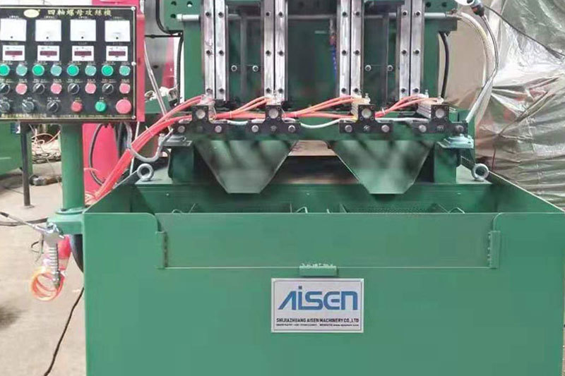
AISEN Four axis nut tapping machine ready for shipment to Russia
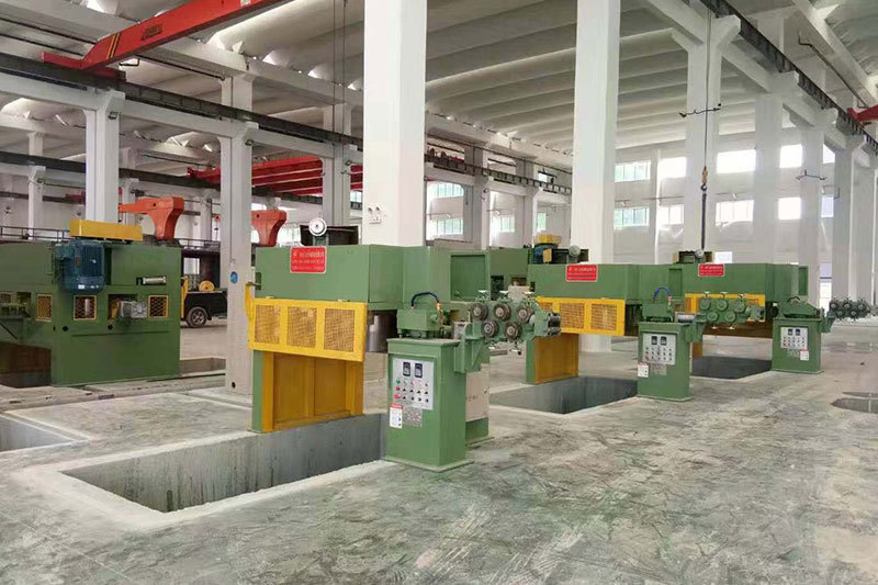
AISEN machinery inverted wire drawing machine
MESSAGES
We will contact you within one working day. Please pay attention to your email.
Qucik Link
Contact
Phone: +86-15100123091
E-mail: info@sjzaisen.com
Address: No.41 Zhaiying South Street, Yuhua District, Shijiazhuang City, Hebei Province China