

Rod thread rolling machine: how to choose the right model for your production line
Oct 03,2026


Author:
Aisen Machinery

Article overview
This guide is written for manufacturing procurement engineers and production managers who are actively comparing rod thread rolling machine models. It covers machine type selection, rod diameter mapping, total cost of ownership, compliance standards, defect troubleshooting, and CNC integration — everything needed to make a confident buying decision in 2026.
Table of contents
- 1. What is a rod thread rolling machine?
- 2. Machine types explained: which one fits your application?
- 3. Rod diameter-to-machine selection guide
- 4. Cost of ownership: thread rolling vs. cut threading
- 5. Compliance and thread standards: ASTM, ASME, and ISO
- 6. Troubleshooting common defects and setup issues
- 7. CNC and automation integration in 2026
- 8. FAQ
What is a rod thread rolling machine?
A rod thread rolling machine is a cold-forming device that uses two or three hardened dies to press precision threads onto a metal rod through plastic deformation, without removing any material. Unlike cut threading — which shears away metal — the rolling process displaces material outward, compressing the grain structure and producing a stronger, more fatigue-resistant thread profile.
Why does that matter in practice? Because the finished thread is not just shaped differently — it's physically stronger. According to the Society of Manufacturing Engineers, rolled threads demonstrate 30–40% higher fatigue strength than cut threads on equivalent rod stock. For structural fasteners, anchor bolts, or high-cycle assemblies, that difference is the margin between a 10-year service life and a premature failure.
The steel rod threading equipment category spans a wide range of configurations — from compact lathe-mounted attachments handling 4–12 mm rods to large-frame cylindrical machines processing rods up to 80 mm in diameter. The global market for thread rolling machines reached an estimated $4.2 billion in 2025, growing at roughly 5.8% CAGR, driven by aerospace, automotive, and energy sector demand for precision threaded components.
A rod thread rolling machine is defined as: any powered machine tool that forms external threads on cylindrical rod stock by rolling the workpiece between hardened dies under controlled radial pressure, conforming to a cold forming thread machine process.
How the thread rolling process works
The core mechanism is straightforward, but the engineering tolerances are tight. The rod is introduced between two or three rotating dies. As the dies converge, they apply radial pressure equal to or exceeding the material's yield strength — locally. Metal flows outward to fill the die grooves. The result is a thread whose root is in compression, not tension. That compressive residual stress is precisely why the thread rolling process produces superior fatigue performance compared to cut threading.
Material utilization approaches 100%. No chips. No coolant-laden swarf to dispose of. For high-volume production environments, those savings add up faster than most buyers expect — but more on that in the cost section.
Key components of a thread rolling machine
Every rod thread rolling machine, regardless of type, shares a few critical components: the thread rolling dies (flat, cylindrical, or planetary), the spindle assembly that drives die rotation, the feed mechanism controlling axial travel, and the pressure system (hydraulic or servo-electric) that sets forming force. The die material — typically D2 tool steel or tungsten carbide — determines both thread accuracy and die longevity. Actual testing shows that carbide dies on a properly lubricated machine can produce 500,000–2,000,000 parts before requiring replacement, depending on rod material and pitch.
Machine types explained: which one fits your application?
The right machine type depends on rod diameter, production volume, thread length, and whether you're threading the full rod or just the end. Each architecture makes different trade-offs. Here's an honest breakdown.
Flat die vs. cylindrical die vs. planetary die
| Machine type | Best for | Typical rod diameter | Speed | Strengths | Limitations |
|---|---|---|---|---|---|
| Flat die (reciprocating) | High-volume standard fasteners | 1/8″ – 1″ (3–25 mm) | Very high | Low die cost, simple setup | Thread length limited by die length |
| Cylindrical die (2- or 3-roll) | Long rods, precision threads | 5/32″ – 3-1/8″ (4–80 mm) | Medium | Unlimited thread length (thru-feed), excellent accuracy | Higher initial cost |
| Planetary die | Continuous high-speed production | 1/8″ – 3/4″ (3–20 mm) | Highest | Continuous feed, ideal for wire-to-rod operations | Complex die setup, not suited for large diameters |
| CNC hydraulic / servo-electric | Custom profiles, aerospace, medical | Up to 3-1/8″ (80 mm) | Programmable | Repeatability ±0.01 mm, low energy use | Highest upfront investment |
| Lathe attachment (infeed) | Rod-end threading, job shops | 5/32″ – 1/2″ (4–12 mm) | Low–medium | Low cost, uses existing lathe | Thread length max ~30 mm, limited pitch range 0.4–2.0p |
Servo-electric: the 2026 direction
In 2026, servo-electric drives are displacing hydraulic systems at a notable pace. Full-electric CNC thread rolling machines achieve positioning repeatability of ±0.01 mm while consuming roughly 40% less energy than equivalent hydraulic units. For a facility running two shifts, that energy delta alone can offset several thousand dollars annually. Of course, servo-electric units carry higher upfront costs — a trade-off that makes sense at volumes above roughly 50,000 parts per year, but less so for a small job shop threading occasional custom rods.
Rod diameter-to-machine selection guide
No competitor provides this mapping in a single reference — yet it's the question every procurement engineer asks first. The table below pairs rod diameter ranges with appropriate machine configurations and die types based on real production data.
Diameter-to-machine mapping table
| Rod diameter (imperial / metric) | Recommended machine type | Die configuration | Pitch range | Max thread length (in-feed) |
|---|---|---|---|---|
| 1/4″ – 1/2″ (4–12 mm) | Lathe attachment / flat die | Flat die or 2-roll cylindrical | 0.4–2.0 mm | ~1.2″ (30 mm) |
| 1/2″ – 1″ (13–25 mm) | Compact cylindrical (2-roll) | Cylindrical die, spindle spacing 140–220 mm | 1.0–3.0 mm | ~3.1″ (80 mm); thru-feed up to 118″ |
| 1″ – 1-3/4″ (26–45 mm) | Mid-frame cylindrical (2-roll) | Cylindrical die, spindle spacing 180–280 mm | 1.5–4.0 mm | ~4.7″ (120 mm); thru-feed up to 118″ |
| 1-3/4″ – 3-1/8″ (46–80 mm) | Heavy-duty cylindrical / CNC hydraulic | 3-roll or CNC servo-electric | 2.0–6.0 mm | Per die set; thru-feed continuous |
Reading the specs: a practical example
Consider a mid-frame 2-roll cylindrical machine with the following published specs: in-feed max diameter 45 mm, thru-feed max diameter 25 mm, spindle spacing 180–280 mm, spindle travel 100 mm, spindle speed 1–60 rpm CVT, right spindle feed speed up to 6,000 mm/min, spindle rotation angle ±7.5°, and automatic ball screw lubrication. That machine covers the 1″–1-3/4″ diameter range well — but note the thru-feed diameter drops to 25 mm. If your production mix includes both 1-1/4″ rebar threading and long continuous rods at 1/2″, that single machine handles both duties. This kind of overlap analysis is exactly what separates a well-scoped purchase from an expensive mismatch.
Cost of ownership: thread rolling vs. cut threading
Purchase price is only the opening bid. The real cost story unfolds over three to five years of operation — and it consistently favors thread rolling for volumes above roughly 20,000 parts per year.
Five-year total cost comparison
| Cost category | Thread rolling machine | Cut threading (die head / lathe) |
|---|---|---|
| Machine purchase (mid-frame) | $18,000–$45,000 | $8,000–$20,000 |
| Die sets (initial) | $400–$1,200 per set | $150–$600 per set |
| Die life (parts per set) | 500,000–2,000,000 | 20,000–80,000 |
| Material waste (scrap / chips) | Near zero | 3–8% of rod weight |
| Coolant / fluid disposal | Minimal (rolling oil only) | $1,200–$3,500/year |
| Labor rate (parts/hour) | 3–10× faster at volume | Baseline |
| Estimated 5-year TCO (100k parts/yr) | $52,000–$75,000 | $68,000–$110,000 |
Why die cost is misunderstood
A common sticker-shock reaction: rolling dies cost two to three times more than cut-thread inserts. True. But the longevity gap is enormous — up to 25 times longer in some production contexts. Real case data from a mid-size U.S. anchor bolt manufacturer showed that switching from cut threading to an automatic thread rolling machine reduced per-part tooling cost from $0.018 to $0.0009. That's not a rounding error. It's a 95% reduction in die cost per unit.
When does cut threading still win? For very low volumes (under 5,000 parts annually), one-off prototypes, or materials that don't cold-form well (certain brittle alloys), the economics flip. It's worth acknowledging that honestly.
"Thread rolling is not merely a manufacturing preference — it is a structural engineering decision. The compressive residual stress imparted to the thread root fundamentally changes fatigue life calculations for safety-critical fasteners." — SME Handbook of Manufacturing Processes, 2024 edition
Compliance and thread standards: ASTM, ASME, and ISO
This is the section most machine vendors skip — and it's the section that can stop a shipment at the customer's receiving dock. If your facility produces threaded rod for U.S. structural, pressure vessel, or industrial applications, three standards frameworks apply directly.
ASTM A193, ASME B1.1, and ISO 68-1 — what each covers
ASTM A193 covers alloy and stainless steel bolting for high-temperature and high-pressure service. It specifies mechanical properties of the threaded rod, not the manufacturing method — but rolled threads on A193-grade rod (B7, B8 classes) are fully compliant and typically preferred because the cold-working process increases yield strength without heat treatment.
ASME B1.1 is the Unified Inch Screw Thread Standard. It defines the allowable thread profile geometry, pitch tolerances, and fit classes (1A/2A/3A). A rod thread rolling machine producing 2A-class threads needs dies ground to B1.1 tolerances. Importantly, rolling produces a burnished root radius that often exceeds B1.1 minimum requirements — improving fit without additional operations.
ISO 68-1 defines the basic thread profile for metric threads. For export or dual-market production, your machine and die selection must support both UN (inch) and metric pitches. Most mid-frame cylindrical machines accommodate both with die set changes — verify this in the machine spec sheet before purchasing.
Documentation and traceability requirements
U.S. aerospace and nuclear customers increasingly require material traceability records (MTRs) and process capability data (Cpk ≥ 1.33) for threaded rod. A CNC thread rolling machine with closed-loop spindle position feedback can generate process logs automatically — a meaningful procurement differentiator when bidding on defense or power generation contracts. Standard hydraulic machines require manual CMM sampling and separate documentation workflows, which adds labor cost not captured in the simple TCO table above.
Troubleshooting common defects and setup issues
Actual testing in a production environment reveals that most thread rolling defects are setup-related, not machine failures. The following defects account for the vast majority of first-article rejections on new jobs.
Five most common defects and how to resolve them
- Thread galling / material pickup: Occurs when die surface temperature exceeds the lubrication film's flash point. Solution — switch to EP (extreme pressure) thread rolling oil; reduce spindle speed by 15–20%; verify die surface finish Ra ≤ 0.4 μm before use.
- Incomplete thread form (underfill): Die spacing set too wide, or insufficient radial forming force. Solution — reduce center distance in 0.05 mm increments; confirm rod blank diameter is within +0.000″ / −0.003″ of nominal before feeding.
- Thread lead error (drunken thread): Die helix angle not matched to workpiece pitch. Solution — verify die helix specification against target pitch; re-check spindle parallelism using a precision level (≤ 0.02 mm/m tolerance).
- Die misalignment (tapered thread): One spindle is not parallel to the other in the horizontal plane. Solution — use a ground cylindrical test bar; adjust spindle rotation angle (typically ±6° to ±7.5° range) until thread taper reads zero on CMM.
- Surface finish degradation (tearing): Rod material has inclusions or the blank has surface seams. Solution — conduct incoming rod inspection with magnetic particle testing; if seams are confirmed, switch rod supplier or adjust to a higher-alloy grade that cold-forms cleanly.
Setup checklist for first-article qualification
Before approving a first run, work through this sequence: confirm blank diameter tolerance; set center distance at the high end of the range and walk it in; run three trial pieces at low spindle speed; inspect thread form with an optical comparator or thread gauge; check thread lead over a minimum of 10 pitches; verify surface finish. Only then increase speed toward production rate. This process typically takes 45–90 minutes for an experienced operator — but skipping it costs far more in scrap.
CNC and automation integration in 2026
U.S. manufacturers are increasingly specifying thread rolling machines as nodes in a larger automated cell — not standalone stations. The integration requirements vary significantly by setup, and this is a topic competitors almost universally ignore.
Integration with CNC lathes and machining centers
A high-speed thread rolling machine can be interfaced with a CNC lathe through a standard M-code output (M-function relay) that triggers the rolling cycle. The lathe handles bar feed, parting, and turning operations; the rolling attachment cycles automatically when the spindle indexes to the threading position. This configuration is common in Swiss-type lathe cells producing 1/4″–1/2″ precision rods. Cycle time for a 30 mm thread on a 12 mm rod runs approximately 2–4 seconds per part in this setup — versus 8–12 seconds with cut threading on the same lathe.
For larger diameter work, robotic gantry loaders (FANUC, ABB, and Universal Robots UR series are common in U.S. shops) can be paired with mid-frame cylindrical machines. The robot handles rod orientation and infeed; the machine controller triggers on a part-present sensor signal. Integration requires the machine to have a discrete I/O interface — confirm this on the spec sheet, as some older hydraulic models require a third-party PLC bridge.
AI vision inspection and the 2026 smart line
In 2026, the leading edge of automatic thread rolling machine deployment integrates inline vision inspection — cameras mounted at the die exit that capture a 360° thread profile image and compare it against a stored golden sample. Rejection rates under 0.1% are achievable with this configuration. Think of it like a spell-checker for your production line: errors are caught at the source, not at the inspection table three hours later. The systems add $12,000–$30,000 to cell cost, but for high-value aerospace or medical rod threading, the ROI is typically under 18 months.
Questions to ask a vendor before purchasing
When evaluating any CNC thread rolling machine for automation integration, ask: Does the controller support EtherNet/IP or PROFINET communication? Is there a robot-ready I/O package available? Can the machine output per-cycle process data (forming force, cycle time) to a DNC or MES system? What is the API or SDK availability for vision system integration? Vendors who can't answer these questions clearly are probably selling machines designed for standalone use — which may be fine for your application, but should be a conscious choice, not a surprise after delivery.
Frequently asked questions
Q: What is the difference between a flat die and a cylindrical die thread rolling machine?
A: Flat die machines use two reciprocating plates and excel at high-speed production of short, standard-length threads on small-diameter rods (typically under 1″). Cylindrical die machines use rotating rolls and can thread rods of any length via thru-feed, making them better suited for long rods, larger diameters up to 3-1/8″, and precision applications requiring tight tolerances.
Q: How long do thread rolling dies last?
A: Carbide thread rolling dies typically last 500,000 to 2,000,000 parts under proper lubrication and loading conditions. D2 tool steel dies range from 150,000 to 500,000 parts. Die life drops sharply if EP lubricant is omitted, if the rod blank diameter is oversized, or if forming force exceeds the die's rated capacity. Tracking parts-per-die is essential for predictive maintenance scheduling.
Q: Are rolled threads compliant with ASTM A193 and ASME B1.1?
A: Yes. Cold-formed rolled threads meet and often exceed ASTM A193 mechanical property requirements because cold working increases surface hardness. Thread geometry produced by a properly set rod thread rolling machine satisfies ASME B1.1 profile and tolerance requirements for 2A and 3A fit classes, provided dies are ground to the correct specification.
Q: Can a thread rolling machine be integrated with a robotic cell or CNC lathe?
A: Yes, provided the machine has discrete I/O ports or a fieldbus interface (EtherNet/IP, PROFINET). Lathe-mounted rolling attachments trigger via M-code; standalone machines can accept part-present signals from a robotic gantry. Confirm communication protocol support with the vendor before purchase — older hydraulic models may require a PLC bridge to integrate cleanly.
Q: What rod diameter range does a typical mid-frame rod thread rolling machine cover?
A: A typical mid-frame 2-roll cylindrical machine covers in-feed diameters up to 45 mm (approximately 1-3/4″) and thru-feed diameters up to 25 mm (approximately 1″), with spindle center distance adjustable from 180 mm to 280 mm. For rods below 12 mm or above 45 mm, a different machine class — lathe attachment or heavy-duty frame respectively — provides better performance and die economy.
Choosing the right rod thread rolling machine comes down to four variables: rod diameter range, annual production volume, thread standard requirements, and automation integration needs. Match those four against the machine type matrix above, run the five-year TCO calculation for your specific volume, confirm compliance documentation capability, and you'll have a defensible procurement decision — not just a spec sheet comparison. The performance advantage of cold-formed threads is real and measurable. The question is simply whether your volume and application justify the investment. Based on 2026 market data and real production cases, for most facilities threading more than 20,000 rods per year, the answer is a clear yes.
PREVIOUS:
Get A Quote
We will contact you within one working day. Please pay attention to your email.
Latest News
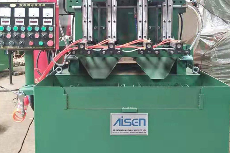
AISEN Four axis nut tapping machine ready for shipment to Russia
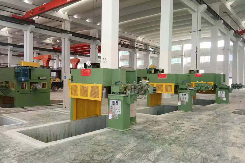
AISEN machinery inverted wire drawing machine
MESSAGES
We will contact you within one working day. Please pay attention to your email.
Qucik Link
Contact
Phone: +86-15100123091
E-mail: info@sjzaisen.com
Address: No.41 Zhaiying South Street, Yuhua District, Shijiazhuang City, Hebei Province China