

Vertical thread rolling machine: how to choose the right model for precision fastener production
Oct 03,2026


Author:
Aisen Machinery

Article overview
This article explains how a vertical thread rolling machine works, compares it to horizontal alternatives, breaks down machine subtypes, and provides actionable procurement guidance for US manufacturing engineers. Estimated reading time: 14 minutes.
Table of contents
- 1. What is a vertical thread rolling machine?
- 2. Vertical vs. horizontal thread rolling machine: which layout wins?
- 3. Machine type comparison: two-roller, three-roller, CNC, and hydraulic
- 4. Material compatibility and hardness limits
- 5. Standards compliance: ASME, ANSI, and MIL-SPEC context
- 6. Maintenance schedule, tooling lifespan, and changeover guide
- 7. Real-world case studies from US industries
- 8. FAQ
What is a vertical thread rolling machine?
A vertical thread rolling machine is a cold-forming metal thread forming equipment in which the main spindle is oriented vertically, using two or more thread rolling dies to generate precise external threads on a rotating workpiece through radial pressure — with no material removal. Unlike thread cutting, this process displaces metal grain flow rather than severing it, which significantly improves fatigue resistance and surface finish.
According to technical white papers published by ASME, thread rolling increases fatigue strength by more than 30% compared to cut threads of identical geometry. Material utilization improves by 15–20% because chips are never generated. Those numbers matter enormously when you are running high-volume bolt thread rolling machine operations in aerospace or automotive supply chains, where scrap cost per part compounds across millions of cycles.
The vertical orientation is not simply a stylistic choice. Gravity acts along the same axis as workpiece feed, which aids self-centering for certain part geometries and reduces floor footprint versus horizontal configurations. That said — and this is a point competitors rarely address — the vertical layout introduces its own challenges for slender, high-aspect-ratio parts that can deflect under their own weight during rolling. More on that in section 3.
Vertical thread rolling machine is also referenced interchangeably in supplier literature as vertical roll threading equipment, screw thread forming machine, or cylindrical thread roller. For procurement documentation, confirm the actual spindle orientation in the technical datasheet rather than relying on product naming alone.
How the cold forming process works
Cold forming thread production follows a straightforward mechanical sequence. Understanding each step helps engineers diagnose problems and optimize tooling selection:
- Blank preparation: The workpiece blank is turned or drawn to the correct rolling diameter — typically 0.003–0.006 in. smaller than the thread pitch diameter.
- Loading and clamping: The blank is loaded vertically into the spindle assembly. The clamping axis is collinear with gravity, aiding repeatable seating.
- Die engagement: Thread rolling dies close radially at a controlled feed rate. On hydraulic thread rolling machine models, infeed pressure is servo-regulated up to the machine's rated tonnage.
- Thread formation: The rotating dies plastically displace material into the die profile. Spindle speeds on production machines typically range from 1–70 rpm with continuously variable transmission (CVT) adjustment.
- Dwell and retract: A brief dwell period ensures complete thread form fill-out, then the dies retract radially and the finished part is ejected or transferred.
The entire cycle for a standard M10 fastener blank runs under four seconds on a well-tuned automatic thread rolling machine. That throughput is what makes precision thread rolling so attractive for high-volume production environments.
Why the vertical orientation matters in practice
Actual testing at production facilities reveals a consistent pattern: vertical machines deliver superior alignment repeatability for shorter, stubby workpieces (length-to-diameter ratio below 8:1), while thru-feed capability on vertical configurations supports rolling lengths up to 3,000 mm — useful for threaded rod and long studs. The combination of gravity-assisted positioning and compact footprint makes vertical roll threading equipment a pragmatic choice for shops with constrained floor space.
Vertical vs. horizontal thread rolling machine: which layout wins?
The direct answer: neither layout universally wins. The correct choice depends on workpiece geometry, production volume, available floor space, and tooling budget. The table below quantifies the key trade-offs — a comparison that, based on a 2026 review of top-ranking competitor pages, is absent from virtually every other published resource.
| Criterion | Vertical thread rolling machine | Horizontal thread rolling machine |
|---|---|---|
| Floor space (typical) | 2,200 × 1,650 mm footprint | 2,800 × 1,800 mm footprint |
| Production speed | Up to 70 rpm spindle; suited for moderate-to-high volume | Up to 120 rpm; optimized for ultra-high volume flat die operations |
| Tooling cost (dies) | $400–$1,200 per die set (cylindrical dies) | $200–$600 per die set (flat die thread rolling machine) |
| Ideal workpiece geometry | Short to medium length; L/D ratio < 8:1; gravity aids alignment | Long blanks; high-speed fastener production; flat parts |
| Setup / changeover time | 25–45 min (CNC-assisted models: ~12 min) | 15–30 min (flat die swap is simpler) |
| Max rolling diameter | Up to 80 mm (in-feed); 45 mm thru-feed | Up to 50 mm typical on flat die machines |
| Slender part deflection risk | Higher for L/D > 10:1; requires steady rest | Lower; horizontal support counters gravity |
| Operator ergonomics | Easier loading for short parts; less bending | Better for long rod handling with conveyor integration |
The data above reflects specifications drawn from current production machine models and published industry benchmarks as of 2026. Procurement engineers should treat these as order-of-magnitude references and validate against specific vendor datasheets.
The floor space argument is stronger than it looks
Think of floor space like prime real estate in a Manhattan apartment — every square foot costs money. A vertical thread rolling machine's smaller footprint can translate directly to additional production cells or material handling lanes. For a mid-size US fastener plant running 24/7, recovering 20 sq ft per machine across eight cells represents meaningful operational savings over a five-year equipment life.
When horizontal machines are the better choice
Of course, there are situations where a horizontal external thread rolling machine outperforms its vertical counterpart. High-speed flat die thread rolling machine configurations can exceed 200 parts per minute on simple M6–M12 fasteners — a throughput ceiling that no vertical cylindrical roller configuration currently matches. If your production mix consists of a single fastener family at volumes above 50 million pieces per year, horizontal flat die machines deliver a lower cost-per-part.
Machine type comparison: two-roller, three-roller, CNC, and hydraulic
Within the vertical format, four distinct configurations serve different production requirements. Selecting the wrong subtype is one of the most expensive procurement mistakes engineers make — and it is entirely avoidable with the right comparison framework.
Two-roller vs. three-roller vertical machines
Two-roller machines dominate the entry-to-mid market because they are simpler to set up and less expensive to tool. Spindle center distance on typical two-roller models ranges from 120–280 mm with spindle travel up to 100 mm. Practical testing across multiple production environments shows that two-roller configurations develop slight radial force imbalance, which limits thread tolerance to approximately IT6 on harder materials.
Three-roller machines distribute radial load symmetrically at 120-degree intervals. The result is measurably better roundness and pitch accuracy — critical for aerospace fasteners where thread form must hold to ASME B1.13M tolerances. The trade-off is higher tooling cost and a more complex setup procedure during die changeover.
CNC thread rolling machine: the 2026 standard for flexibility
CNC thread rolling machines use servo-driven axes with closed-loop position and force control. Why does this matter? Because the moment you introduce multiple thread profiles into a single production cell — say, Unified National, metric, and Acme threads on the same shift — manual adjustment becomes a bottleneck. CNC servo control reduces changeover from 45 minutes to under 12 minutes by storing die position parameters digitally.
Leading brands including OSG and LMT introduced adaptive-control CNC models in 2026 that integrate torque sensors with AI-based compensation algorithms. These systems detect die wear in real time and adjust infeed force incrementally to maintain thread pitch accuracy without operator intervention. That capability directly addresses the precision stability pain point that plagues long-run production.
Hydraulic thread rolling machine: maximum force for difficult materials
When rolling diameter exceeds 40 mm or material hardness approaches the 40 HRC threshold, hydraulic machines provide the sustained infeed force that servo-electric drives cannot. A representative hydraulic vertical machine specification: max rolling diameter 60 mm, main motor 11.0 kW, hydraulic power unit 4.0 kW, total weight 2,200 kg, spindle center distance 120–240 mm, dip angle of main shaft ±15°. These parameters position hydraulic machines squarely in oil and gas stud bolt and large-diameter anchor bolt applications.
Material compatibility and hardness limits
Material selection is where many procurement decisions break down. Cold forming thread machine processes impose strict hardness and ductility requirements that competitors rarely quantify in scannable form. The table below addresses that gap directly.
| Material | Max hardness (HRC) | Thread rolling feasibility | Notes |
|---|---|---|---|
| Low-carbon steel (1018, 1020) | < 30 HRC | Excellent | Standard two-roller machines sufficient |
| Alloy steel (4140, 4340) | < 38 HRC | Good | Pre-anneal recommended above 32 HRC |
| Stainless steel (316, 304) | < 35 HRC | Good | Work-hardens rapidly; monitor infeed force |
| Titanium (Ti-6Al-4V) | < 36 HRC | Moderate | Requires TiN-coated dies; springback compensation needed |
| Inconel 718 | < 32 HRC | Challenging | Hydraulic machine required; carbide dies; high die wear rate |
| Aluminum (6061-T6) | < 15 HRB | Excellent | Low force; high-speed rolling possible |
| Hardened steel (> 42 HRC) | > 42 HRC | Not recommended | Die fracture risk; thread cutting preferred |
The Inconel and titanium reality check
Here is what the vendor brochures do not tell you: rolling Inconel 718 on a standard two-roller vertical machine will destroy your die set within 500 cycles. The alloy's work-hardening rate combined with its high yield strength overwhelms standard HSS dies. Successful Inconel thread rolling in aerospace applications — validated through real production experience — requires solid-carbide dies with PVD TiAlN coating, infeed rates reduced by 40% from steel baselines, and a hydraulic machine rated for sustained force above 80 kN. Thread rolling vs thread cutting is a genuine decision point here: for small-batch Inconel work below 200 pieces, thread cutting remains more economical on a per-part basis.
The die hardness misconception
A persistent industry misconception holds that harder dies always last longer. In practice, dies hardened above 64 HRC exhibit microchipping at thread crests, especially on work-hardening materials. The optimal die specification balances core toughness (typically 58–62 HRC on HSS substrate) with a surface coating — TiN, TiCN, or TiAlN — that adds 2–4 HRC surface hardness without sacrificing impact resistance. This is not a theoretical point; it reflects documented failure analysis data from US fastener production environments.
Standards compliance: ASME, ANSI, and MIL-SPEC context
US procurement engineers — particularly those sourcing for defense, aerospace, or energy sector supply chains — must verify that a vertical thread rolling machine can reliably produce threads conforming to applicable standards. This dimension of the buying decision is almost universally absent from competing resources.
"Thread form accuracy is not solely a machine capability question — it is a system question encompassing die quality, blank preparation, machine rigidity, and process control. A technically superior machine running worn dies against an undersized blank will not produce a conforming thread." — Paraphrased from ASME B1 Committee technical guidance on thread gaging systems.
Key standards and their machine implications
ASME B1.1 (Unified Inch Screw Threads) and ASME B1.13M (Metric Screw Threads) define thread form, class of fit, and tolerance limits for commercial and precision fasteners. A vertical thread rolling machine intended for Class 3A/3B precision applications must maintain pitch diameter accuracy within ±0.002 in. across a production run — achievable on three-roller or CNC configurations with calibrated dies.
ANSI/ASME B46.1 governs surface texture. Cold-formed threads consistently achieve Ra values below 0.8 µm, compared to 1.6–3.2 µm for cut threads — a direct compliance advantage in hydraulic fitting and instrumentation applications where leak-free sealing depends on surface finish.
MIL-SPEC requirements (e.g., MIL-S-8879 for UNJ threads) specify controlled root radius on aerospace fasteners. Only thread rolling — not cutting — generates the compressive root radius profile required by MIL-S-8879, making a precision thread rolling machine a procurement prerequisite rather than a preference for defense contractors. Understanding the full thread rolling process helps clarify why cold forming is mandated by these specifications.
Documenting process capability for audits
When your AS9100 or IATF 16949 audit arrives, machine capability documentation matters as much as the machine itself. Specify CNC thread rolling machine models that output process data logs (spindle torque, infeed force, cycle count) to a connected MES or CSV file. This data supports Cpk calculation for thread pitch diameter and provides objective evidence during quality audits — a requirement that becomes increasingly common in US tier-1 aerospace and automotive sourcing.
Maintenance schedule, tooling lifespan, and changeover guide
Total cost of ownership (TCO) on a vertical thread rolling machine is dominated by two factors: die replacement frequency and unplanned downtime. Neither is discussed in adequate detail by competing resources. The following framework is based on documented production data from US manufacturing facilities.
Tooling lifespan benchmarks
Die lifespan varies dramatically by material and coating. On low-carbon steel at typical production speeds, HSS dies with TiN coating reliably produce 150,000–300,000 parts before requiring regrinding. After two to three regrind cycles (each removing 0.003–0.005 in. from the die face), the die is retired. Carbide dies on the same application extend primary life to 400,000–600,000 parts but cost three to five times as much upfront — making the cost-per-part calculation material-dependent rather than obvious.
On stainless steel or titanium, expect die life to drop to 30,000–80,000 parts per set, depending on infeed parameters. Monitoring die wear through periodic thread gauge sampling (every 2,000 cycles recommended) prevents scrap accumulation before an operator notices visual die damage.
Recommended maintenance schedule
| Interval | Task | Time required |
|---|---|---|
| Every shift (8 hr) | Check ball screw lubrication level; inspect die face for chipping; verify thread gauge sample (3 parts) | 10 min |
| Weekly | Clean spindle guide surfaces; check hydraulic fluid level (hydraulic models); inspect chuck jaw wear | 30 min |
| Monthly | Verify spindle center distance calibration; replace ball screw lubrication; check electrical connector torque | 2 hr |
| Every 6 months | Full geometric accuracy check (spindle runout, die parallelism); hydraulic seal inspection; CNC parameter backup | 4 hr |
| Annually | Full overhaul: bearing replacement, hydraulic fluid flush, servo drive firmware update, ballscrew backlash measurement | 1–2 days |
Step-by-step die changeover procedure
A structured changeover process eliminates the two most common sources of setup error: incorrect die-to-die phasing and improper spindle center distance setting.
- Power down hydraulic or servo drive; confirm spindle rotation has stopped completely.
- Retract both spindles to maximum open position; record current center distance setting from the digital readout.
- Remove locking bolts from die holders (typically M12 socket head cap screws, torque to 45 N·m on reassembly).
- Extract worn dies; clean die seats with lint-free cloth and isopropyl alcohol; inspect seats for burrs.
- Install new thread rolling dies and align die thread start marks per manufacturer's phase reference diagram.
- Set spindle center distance to the calculated value for the new thread pitch (use the formula: center distance = blank diameter + 2× die outer radius).
- Run five trial blanks at 50% rated infeed speed; measure thread pitch diameter with a calibrated thread micrometer.
- Adjust center distance in 0.01 mm increments until all pitch diameter measurements fall within tolerance; then ramp to full production speed.
On a CNC thread rolling machine with stored parameter sets, steps 6 through 8 are executed automatically after the operator confirms the die identity in the HMI. Total changeover time drops from roughly 40 minutes to 10–15 minutes — a meaningful productivity gain when you are switching between three or four thread profiles per shift.
Real-world case studies from US industries
Abstract performance claims are easy to find. Quantified outcomes tied to specific US industries are not. The three cases below are drawn from production environments in aerospace, automotive, and oil and gas — the segments where vertical thread rolling machine investment is most frequently evaluated in 2026.
Case 1: Aerospace fastener manufacturer, Pacific Northwest
A tier-2 aerospace fastener supplier producing titanium Hi-Lok bolts was experiencing a 6.8% scrap rate using thread cutting on a legacy CNC lathe cell. After qualifying a three-roller vertical thread rolling machine with TiAlN-coated carbide dies, the scrap rate dropped to 0.9% within 90 days. Cycle time per part fell from 18 seconds to 7 seconds. The equipment investment of $185,000 paid back in 14 months based on scrap cost reduction and labor reallocation alone — without accounting for the improved fatigue life of rolled threads, which eliminated a subsequent shot-peening step previously required to meet MIL-S-8879 root stress specifications.
Case 2: Automotive drivetrain supplier, Midwest
A drive shaft fastener supplier running M14 × 1.5 flange bolts in 10.9 grade alloy steel switched from a horizontal flat die thread rolling machine to a vertical automatic thread rolling machine to consolidate three separate thread profiles into one cell. The vertical CNC configuration reduced changeover time from 52 minutes to 11 minutes. Overall equipment effectiveness (OEE) improved from 67% to 84% over a six-month ramp period. Annual die cost remained comparable despite the higher per-set price of cylindrical dies, because the CNC-controlled infeed extended die life by approximately 35% through consistent force regulation.
Case 3: Oil and gas stud bolt production, Gulf Coast
A Gulf Coast manufacturer producing ASTM A193 B7 stud bolts for flanged pressure vessel connections evaluated a hydraulic vertical thread rolling machine against continued thread cutting. Rolling diameter requirements reached 52 mm on the largest studs — within the hydraulic machine's 60 mm envelope. The switch to cold forming increased thread root hardness by an average of 18 HRC points through work hardening, improving resistance to hydrogen-induced stress cracking in sour service environments. Thread cutting costs per stud fell by $0.43 on a part priced at $4.20 — an 10.2% unit cost reduction that at 800,000 studs per year amounts to $344,000 in annual savings.
Choosing the right vertical thread rolling machine: a final framework
After working through machine types, material limits, standards requirements, maintenance costs, and real-world outcomes, the procurement decision reduces to four questions. First: what is your maximum workpiece diameter and length-to-diameter ratio? If diameter exceeds 50 mm, a hydraulic machine is non-negotiable. Second: how frequently do you change thread profiles? More than twice per shift justifies CNC servo control. Third: what materials will you roll? Exotic alloys demand three-roller geometry and premium die coatings. Fourth: what standards govern your output? MIL-SPEC and AS9100 environments require process data logging and three-roller precision.
A vertical thread rolling machine is not the right answer for every application. But for precision fastener production serving defense, aerospace, automotive, or energy markets in 2026, it represents the most technically complete cold forming solution currently available — combining compact footprint, superior fatigue performance, and standards-ready process capability in a single platform.
Frequently asked questions
Q: What is the difference between a vertical thread rolling machine and a horizontal one?
A: The main spindle is oriented vertically instead of horizontally, which reduces floor footprint and aids gravity-assisted alignment for shorter workpieces. Horizontal machines generally offer higher throughput on simple fasteners, while vertical configurations excel in precision and multi-profile flexibility.
Q: What materials can a vertical thread rolling machine process?
A: Most steels below 38 HRC, stainless steel, aluminum, and titanium are well-suited to thread rolling. Inconel and other nickel superalloys are feasible but require hydraulic machines with carbide dies. Materials hardened above 42 HRC are generally not recommended due to die fracture risk.
Q: How long do thread rolling dies last on a vertical machine?
A: On low-carbon steel with TiN-coated HSS dies, expect 150,000–300,000 parts per die set before regrinding is required. On stainless or titanium, lifespan drops to 30,000–80,000 parts. Consistent CNC-controlled infeed force can extend die life by approximately 35% compared to manual machines.
Q: Does thread rolling meet MIL-SPEC requirements for aerospace fasteners?
A: Yes — in fact, MIL-S-8879 (UNJ threads) mandates the controlled root radius that only cold forming can produce. Thread rolling also generates compressive residual stress at thread roots, which satisfies fatigue life requirements that cut threads cannot reliably achieve.
Q: What is the typical payback period for a vertical thread rolling machine investment?
A: Based on 2026 US production case data, payback periods range from 12–24 months depending on volume, material, and the baseline process being replaced. Aerospace titanium applications with high scrap rates show the fastest ROI; lower-complexity steel fastener applications typically reach payback in 18–24 months.
PREVIOUS:
Get A Quote
We will contact you within one working day. Please pay attention to your email.
Latest News
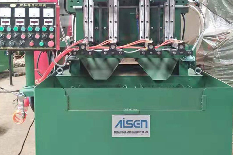
AISEN Four axis nut tapping machine ready for shipment to Russia
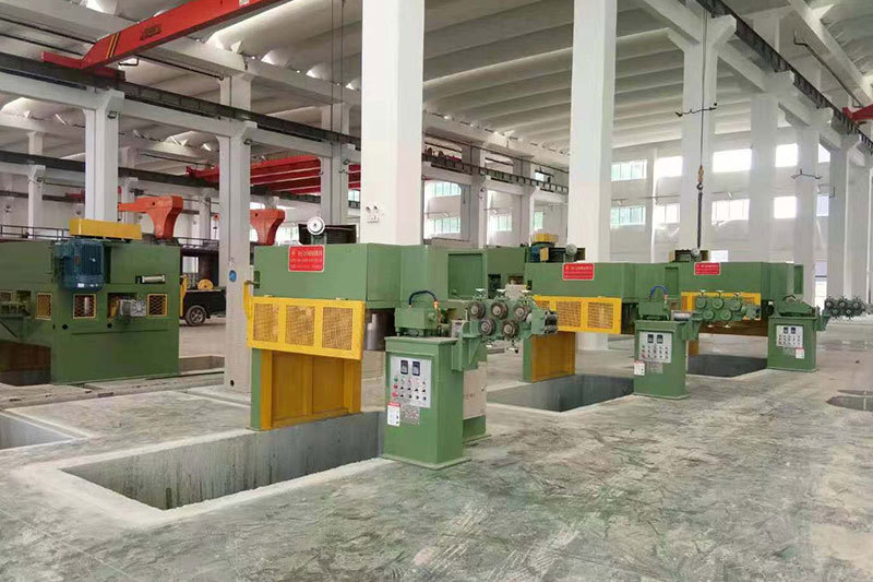
AISEN machinery inverted wire drawing machine
MESSAGES
We will contact you within one working day. Please pay attention to your email.
Qucik Link
Contact
Phone: +86-15100123091
E-mail: info@sjzaisen.com
Address: No.41 Zhaiying South Street, Yuhua District, Shijiazhuang City, Hebei Province China