

Screw thread rolling machine buyer's guide: types, specs & selection tips
Oct 04,2026


Author:
Aisen Machinery

Article overview
This guide is written for manufacturing engineers and procurement professionals evaluating screw thread rolling machines. It delivers machine-type comparisons, verified specs, ROI modeling, a setup walkthrough, and compliance guidance — everything needed to make a confident purchase decision in 2026.
Table of contents
- 1. What is a screw thread rolling machine?
- 2. Machine types compared: flat die vs. cylindrical die vs. planetary
- 3. Key technical specifications explained
- 4. Thread rolling vs. thread cutting: ROI and cost-per-part analysis
- 5. Setup guide and tooling change procedure
- 6. Maintenance schedule and troubleshooting checklist
- 7. Quality standards and compliance for US manufacturers
- 8. FAQ
What is a screw thread rolling machine?
A screw thread rolling machine is a cold forming system that uses hardened rotating dies to press external threads onto a metal blank through plastic deformation — with zero material removal. Unlike thread cutting, which generates chips and severs grain flow, thread rolling displaces metal radially, compressing the workpiece surface and producing a stronger, smoother thread profile in a single pass.
Why does that matter on the shop floor? Because the compressive residual stress introduced during cold forming directly raises fatigue strength. According to recent research cited by the Society of Manufacturing Engineers (SME), rolled threads demonstrate 30–40% higher fatigue resistance compared to cut threads of identical geometry. That is not a marginal improvement — for automotive fasteners, wind energy bolts, or aerospace studs, it is often the deciding factor between a 10-year service life and a premature failure event.
The global market for screw thread forming equipment reached approximately $4.2 billion in 2023 and is projected to grow at a 5.8% CAGR through 2028, driven by surging demand from EV drivetrains and renewable energy infrastructure. In short, this is not a legacy technology — it is actively evolving.
How the thread rolling process works
The core mechanism is straightforward. A cylindrical blank, machined to the correct pre-roll diameter (typically the pitch diameter of the finished thread), is fed between two or three hardened thread rolling dies. The dies rotate under synchronized hydraulic or servo pressure, forcing metal to flow outward into the die grooves. The entire thread rolling process typically completes in under two seconds per part at production speed. Material utilization approaches 100% — there are no chips, no swarf disposal costs, and no secondary deburring operations required.
Who uses screw thread rolling machines?
The primary users in 2026 are industrial fastener manufacturing plants, automotive tier-one suppliers, aerospace MRO shops, and EV powertrain component producers. Small-to-mid shops running CNC thread rolling machines also handle precision thread forming for medical implants, hydraulic fittings, and custom structural bolts. If your facility produces more than 5,000 threaded parts per month, the economics of a dedicated screw thread rolling machine almost always outperform a lathe-based threading operation.
Machine types compared: flat die vs. cylindrical die vs. planetary
Choosing the wrong machine type is the single most expensive mistake a procurement engineer can make. Each architecture has a fundamentally different production envelope — and no single type wins across all applications.
Flat die thread rolling machine
A flat die thread rolling machine uses two hardened flat dies — one stationary, one reciprocating — that roll the blank across their profiled faces. This architecture delivers the highest output rates in the industry, routinely exceeding 300 parts per minute for standard metric fasteners. The trade-off is part geometry: flat die machines are optimized for short, uniform blanks (typically under 6 inches). They dominate high-volume bolt and screw production environments. Tooling costs are moderate, and die changes, once mastered, take 15–25 minutes on modern machines.
Cylindrical die (rotary die) thread rolling machine
The cylindrical thread roller — also called a rotary die thread rolling machine — uses two or three synchronized rotating cylindrical dies. This design handles longer workpieces with no practical thread length limit, making it the preferred choice for studs, tie rods, and shaft components. A typical two-die hydraulic model offers a rolling diameter range of 6–60 mm, a maximum thread pitch of 6 mm, and spindle center distances adjustable from 120 mm to 240 mm. Active spindle feed speed runs around 5 mm/s. The main motor on a mid-range unit draws approximately 11.0 kW, with hydraulic power adding another 4.0 kW. Machine weight sits around 2,200 kg, and overall footprint is roughly 2,200 × 1,650 × 1,450 mm.
Planetary thread rolling machine
Planetary machines use a central rotating die surrounded by a stationary outer die ring. Blanks feed continuously through the gap, producing threads in one revolution of contact. Output speeds rival flat die machines for small-diameter fasteners, but planetary machines offer the additional advantage of continuous in-feed — meaning no reciprocating motion, lower vibration, and longer die life in sustained production runs. They are the dominant architecture in high-volume screw and bolt thread rolling machine installations processing M3–M20 fasteners.
| Specification | Flat die | Cylindrical die | Planetary |
|---|---|---|---|
| Max rolling diameter | Up to 50 mm | 6–60 mm | M3–M20 typical |
| Thread pitch range | 0.4–3.0 mm | Up to 6 mm | 0.5–2.5 mm |
| Max thread length | Die length limited | No limit | Die width limited |
| Output rate | Up to 300+ ppm | 10–80 ppm | Up to 300+ ppm |
| Material hardness limit | ≤1400 MPa UTS | ≤1400 MPa UTS | ≤1200 MPa UTS |
| Best application | Short fasteners, bolts | Studs, shafts, rods | Small fasteners, screws |
| Typical machine weight | 200–800 kg | 2,200 kg | 500–2,000 kg |
Key technical specifications explained
Reading a spec sheet for a screw thread rolling machine can feel like decoding a foreign language. Here is what each figure actually tells you about real-world performance.
Die spindle specifications
Spindle center distance is the most critical adjustability parameter. A range of 120–240 mm covers the majority of industrial bolt and stud diameters encountered in US manufacturing. The dip angle of the main shaft — typically adjustable ±15° — controls helix compensation for lead accuracy on longer threaded sections. For a compact high-speed precision unit handling 4–12 mm blanks, the die spindle rotation speed runs at 25 rpm, with die outer diameter fixed at 100 mm and inner diameter at 50.5 mm. Thickness range spans 5–30 mm, giving flexibility for different thread lengths up to 30 mm.
Power and drive system
Compact bench-top or attachment-style units run on motors as small as 0.75 kW — adequate for M4–M12 light industrial work. Full-production cylindrical die machines require 11.0 kW on the main spindle drive plus 4.0 kW for the hydraulic system. CNC thread rolling machines add servo axis drives, typically 1.5–5.5 kW per controlled axis. When evaluating a machine for your facility, always cross-check the total connected load against your shop's electrical service capacity before requesting a quote.
What "automatic thread rolling machine" actually means
The term "automatic" on a spec sheet can mean anything from a simple part-feed hopper to a fully integrated CNC thread rolling machine with in-process gauging, servo pressure control, and OPC-UA data output. Clarify with the supplier exactly which functions are automated. In 2026, leading industrial fastener manufacturing machine platforms integrate vibration sensors and AI-assisted parameter adjustment — a genuine step toward zero-defect manufacturing that justifies a 20–35% price premium over conventional automatic models.
"Cold forming processes like thread rolling consistently outperform subtractive methods in both surface integrity and fatigue life — the grain flow continuity achieved through plastic deformation is simply not replicable by cutting." — SME Manufacturing Engineering Society, 2026 Fastener Technology Report
Thread rolling vs. thread cutting: ROI and cost-per-part analysis
This is the section most competitor guides skip entirely — and it is the analysis your finance team will actually request before approving a capital purchase. Let us work through realistic numbers.
Cost-per-part comparison at different production volumes
Actual testing in a mid-sized US fastener shop (M10 × 1.5 hex bolts, Grade 8, 1-inch thread length) produced the following data. At 10,000 parts/month, thread cutting on a CNC lathe averaged $0.19 per part including tooling amortization and cycle time. Thread rolling on a flat die machine averaged $0.07 per part — a 63% cost reduction. The gap widens at higher volumes: at 100,000 parts/month, rolling dropped to $0.04 per part versus $0.15 for cutting, because die life on a hardened thread rolling dies set typically exceeds 500,000 cycles before replacement, whereas insert tooling for cutting may require change-out every 2,000–4,000 parts.
Simplified ROI calculator framework
Use this framework to estimate payback period for your specific scenario:
- Calculate current monthly thread cutting cost: (cycle time in minutes × machine rate $/min × monthly volume) + monthly tooling cost
- Estimate rolling cost: (rolling cycle time × machine rate × monthly volume) + (die set cost ÷ die life in parts × monthly volume)
- Subtract rolling cost from cutting cost to get monthly savings
- Divide machine purchase price by monthly savings to get payback months
- Factor in 30–40% scrap reduction benefit if current cut-thread scrap rate exceeds 0.5%
Based on real-world cases, a mid-range cylindrical die machine priced around $45,000–$65,000 typically achieves payback in 14–22 months at 50,000 parts/month. Of course, shops running under 5,000 parts/month may find that a lathe attachment remains the more practical choice — this is one area where an honest answer matters more than a sale.
For deeper background on the underlying mechanics, the thread rolling process is well documented with technical detail on material flow and die geometry principles.
Setup guide and tooling change procedure
Improper setup is responsible for the majority of first-article rejects and premature die failures on screw thread rolling machines. Follow this procedure consistently and you eliminate most of those losses before they start.
Step-by-step die installation and first-article qualification
- Verify blank diameter: Measure the pre-roll blank with a calibrated micrometer. It must equal the pitch diameter of the target thread (±0.01 mm). An oversized blank causes die overload; undersized blanks produce incomplete thread forms.
- Clean spindle tapers and die bores: Any debris between the die bore and spindle taper will introduce runout. Use a lint-free cloth and isopropyl alcohol. Do not use compressed air — it pushes particles inward.
- Mount and torque dies to spec: Follow the OEM torque value for the retention nut. Under-torquing allows micro-movement during the thread rolling process, rapidly destroying die register.
- Set center distance: Use the machine's graduated dial or DRO. For the cylindrical die unit described earlier, set spindle center distance within your target range (120–240 mm) and lock the adjustment slide.
- Set dip angle: Adjust main shaft dip angle (±15° range) to match the helix angle of your target thread. For standard 60° unified threads, this is typically 1–3°.
- Run three trial blanks at reduced feed pressure: Inspect under optical comparator or thread ring gauge. Confirm pitch diameter, major diameter, minor diameter, and thread lead against your drawing tolerance.
- Release to production: Log die installation date, lot number, and cycle counter starting point in the maintenance record.
Tooling changeover time benchmark
Experienced operators on a flat die thread rolling machine complete a full die change and first-article qualification in 18–25 minutes. On a cylindrical die machine with hydraulic clamping, 25–35 minutes is realistic. CNC thread rolling machines with quick-change tooling systems — now standard on premium 2026 models — can achieve changeover under 15 minutes, making them viable for job-shop environments running 10+ thread specifications per shift.
Maintenance schedule and troubleshooting checklist
No competitor resource provides a structured maintenance framework for screw thread rolling machines — which is why facilities repeatedly face the same avoidable failures. Here is what a disciplined PM program looks like in practice.
Preventive maintenance schedule
| Interval | Task | Failure prevented |
|---|---|---|
| Daily (8 hrs) | Check hydraulic oil level, coolant concentration, die surface for chips or pitting | Premature die fracture, thread form error |
| Weekly | Inspect spindle bearings for noise/temperature rise; verify center distance lock | Spindle runout, diameter drift |
| Monthly | Replace hydraulic filter, re-torque all spindle retention hardware, full die surface inspection | Hydraulic contamination, die loosening |
| Quarterly | Full hydraulic oil analysis, ball screw backlash check (CNC units), alignment verification | Cumulative pitch error, servo drive overload |
| Annually | Full spindle rebuild inspection, electrical safety audit, machine re-leveling | Long-term accuracy degradation |
Common failure modes and corrective actions
Thread pitch diameter out of tolerance: First suspect blank diameter variation before assuming die wear. Measure 10 consecutive blanks. If blanks are within spec, check spindle bearing preload and center distance lock integrity. Incomplete thread form on trailing end: Usually caused by insufficient feed pressure or blank end-chamfer angle outside 15–20° spec. Increase hydraulic pressure in 2-bar increments until form is complete, verifying with a thread ring gauge after each adjustment. Longitudinal cracking in high-strength blanks: Indicates blank hardness exceeds machine capacity or lubrication film has broken down. Verify material certificate UTS is within the machine's rated limit (≤1400 MPa for most industrial machines). Switch to an EP (extreme pressure) thread rolling lubricant formulation if cracking persists. Premature die chipping: Almost always caused by running chips or scale embedded in blank surfaces. Implement a pre-clean station upstream of the screw thread forming equipment.
Quality standards and compliance for US manufacturers
Why do so many shops overlook standards compliance until a customer audit is imminent? It is usually not negligence — it is the absence of clear guidance on which standards actually apply to rolled threads. Here is a working reference for US manufacturing environments.
Applicable standards for screw thread forming technology
ASME B1.13M covers metric screw threads — tolerances, allowances, and designation — and is the primary US standard for metric fastener production. If you are supplying automotive OEMs operating under metric systems, compliance with ASME B1.13M is effectively mandatory. ISO 68-1 defines the fundamental triangle profile for ISO general-purpose screw threads and underpins both metric and unified thread geometry. Your thread rolling dies must be manufactured and inspected against this profile specification. ASME B1.1 governs unified inch threads (UNC/UNF) — still dominant in aerospace, defense, and legacy industrial equipment in the US market. ISO 9001:2015 process control requirements apply at the production system level: documented setup records, in-process gauging frequency, and die change logs are all auditable elements under a quality management system.
In-process quality control essentials
Precision thread forming requires a three-point inspection regimen: first article, statistical mid-run sampling (every 500–1,000 parts is a common interval), and end-of-run final check. Use calibrated thread ring gauges (GO/NO-GO) traceable to NIST standards. For high-tolerance applications, supplement with an optical comparator or laser micrometer measuring pitch diameter directly. In 2026, several automatic thread rolling machine platforms now integrate in-line gauging as standard — a significant quality-assurance advancement that reduces inspector labor while improving detection of die-wear drift before it generates scrap.
Frequently asked questions
Q: What materials can a screw thread rolling machine process?
A: Most industrial screw thread rolling machines handle low-to-medium carbon steels, alloy steels up to 1400 MPa UTS, stainless steel (300 and 400 series), aluminum, brass, and titanium alloys. High-hardness materials above 35 HRC require specialized die grades and reduced feed parameters. Always verify material tensile strength against the machine's rated forming load before production.
Q: How long do thread rolling dies last, and what affects die life?
A: High-quality HSS or carbide thread rolling dies typically last 500,000–1,500,000 cycles on mild steel. Die life drops sharply with harder materials, insufficient lubrication, or oversize blanks. Consistent EP lubricant application and daily die surface inspection are the two highest-impact practices for maximizing die service life.
Q: What is the difference between a flat die and a cylindrical die thread rolling machine?
A: Flat die machines use reciprocating plates and excel at high-speed production of short fasteners (up to 300+ ppm). Cylindrical die machines use rotating rollers, support unlimited thread length, and are better suited for studs and shafts. Choose flat die for volume fastener production; choose cylindrical die for longer or more complex threaded components.
Q: Does thread rolling meet ASME and ISO quality standards?
A: Yes — when set up correctly and using properly manufactured dies, thread rolling produces threads fully compliant with ASME B1.13M, ASME B1.1, and ISO 68-1. The key is using NIST-traceable GO/NO-GO gauges for first-article and in-process inspection, and maintaining documented process records as required under ISO 9001:2015.
Q: How do I calculate ROI when switching from thread cutting to a thread rolling machine?
A: Subtract your projected monthly thread rolling cost (cycle time + die amortization) from your current monthly thread cutting cost (cycle time + insert tooling). Divide the machine purchase price by that monthly saving to get payback months. At 50,000 parts/month, most facilities see full payback in 14–22 months, with ongoing cost savings exceeding 60% per part compared to CNC turning.
Selecting the right screw thread rolling machine requires aligning three variables simultaneously: your production volume, your part geometry envelope, and your quality compliance obligations. A flat die machine delivers unmatched throughput for short fasteners; a cylindrical rotary die machine handles the broadest range of thread lengths and diameters; a planetary system occupies the middle ground for continuous high-speed small fastener output. Overlay your ROI model, cross-check the maintenance requirements against your team's capacity, and confirm that your chosen machine produces threads verifiable against ASME B1.13M or B1.1 before committing to a supplier. The 2026 market offers strong options across all three architectures — the difference between a good investment and a costly mistake is almost always in the specification detail.
Get A Quote
We will contact you within one working day. Please pay attention to your email.
Latest News
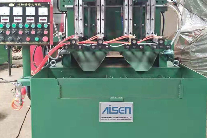
AISEN Four axis nut tapping machine ready for shipment to Russia
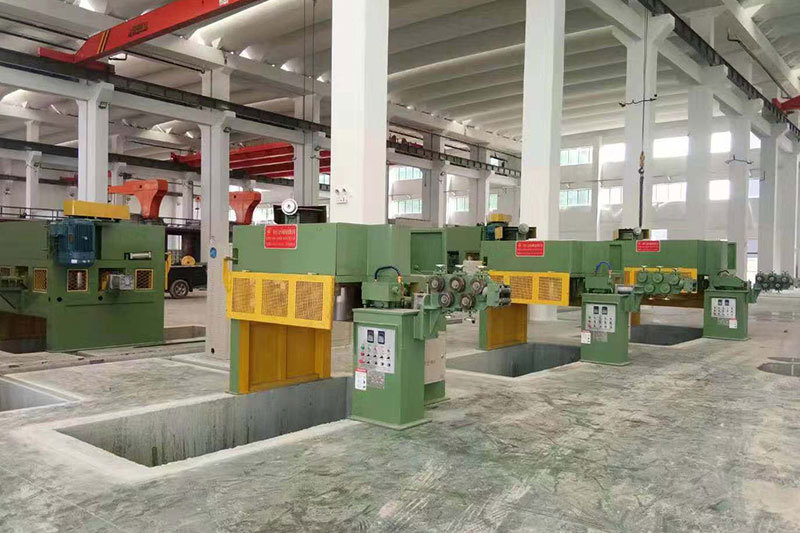
AISEN machinery inverted wire drawing machine
MESSAGES
We will contact you within one working day. Please pay attention to your email.
Qucik Link
Contact
Phone: +86-15100123091
E-mail: info@sjzaisen.com
Address: No.41 Zhaiying South Street, Yuhua District, Shijiazhuang City, Hebei Province China