

Screw machine thread rolling: process guide, tips, and how it works
Oct 04,2026


Author:
Aisen Machinery

Article overview
This guide provides a complete technical reference for screw machine thread rolling in 2026, covering process mechanics, material parameters, blank diameter formulas, cost benchmarking, die life management, and defect troubleshooting. Intended for manufacturing engineers and procurement professionals evaluating cold-forming thread options for automatic and CNC screw machine production.
Table of contents
- 1. What is screw machine thread rolling?
- 2. How the thread rolling process works on screw machines
- 3. Material-specific parameters for screw machine threading
- 4. Blank diameter calculation: the formula you actually need
- 5. Thread rolling vs. thread cutting on screw machines
- 6. Die life benchmarks and wear management
- 7. Troubleshooting common screw machine thread rolling defects
- 8. FAQ
What is screw machine thread rolling?
Screw machine thread rolling is a cold-forming process in which hardened dies apply radial pressure to a rotating metal blank on an automatic screw machine, displacing material to form precise threads without removing any chips. Unlike thread cutting, no material is lost — the grain structure flows continuously, producing stronger, smoother threads in a single, high-speed operation.
For engineers running automatic screw machine or CNC Swiss-type equipment, the appeal is immediate: the thread rolling process integrates directly into the machine cycle, adding virtually zero extra cycle time while delivering a rolled thread fastener with measurably superior fatigue resistance. According to 2026 data from the Industrial Fasteners Institute (IFI), rolled threads exhibit 15%–30% higher fatigue strength than equivalent cut threads — a margin that matters in automotive, aerospace, and medical device applications where thread failure carries serious consequences.
Why do so many shops still default to thread cutting, then? Inertia, partly. And partly a genuine misunderstanding of what screw machine thread rolling actually requires in terms of setup. This guide addresses both.
Core mechanics of cold forming threads
Cold forming threads works by pressing a hardened die — flat, cylindrical, or planetary — against a pre-turned blank that is rotating at the correct diameter. The die teeth displace metal radially inward and outward simultaneously, forming the thread root and crest without cutting. The result is a work-hardened surface with compressive residual stress at the root, which is precisely why rolled threads resist fatigue crack initiation far better than cut threads. Surface roughness routinely reaches Ra ≤ 0.4 μm — better than most turning operations can achieve.
Where screw machine thread rolling fits in the production landscape
Screw machine parts production spans everything from standard hex-head fasteners to intricate Swiss-turned medical pins. In high-volume runs — typically above 10,000 pieces — screw machine thread rolling delivers a compelling cost-per-part advantage. The process scales cleanly from Brown & Sharpe multi-spindle automatics to modern CNC Swiss screw machines running bar stock thread rolling operations at cycle times under three seconds per part.
How the thread rolling process works on screw machines
The mechanics are straightforward, but precise sequencing matters. On a typical automatic screw machine, thread rolling attachments mount at a cross-slide or end-working position and engage the blank during the same cycle window as other forming operations.
Step-by-step process sequence
- Bar stock preparation: The bar stock is fed and the blank is turned to the precise pre-roll diameter (see Section 4 for the calculation formula).
- Die engagement: The thread rolling attachment advances, bringing the flat die or cylindrical die into contact with the rotating blank at a controlled infeed rate.
- Forming stroke: Radial pressure builds as the die penetrates to the required depth. The material flows plastically, forming the thread profile over 1–3 full rotations depending on thread pitch and material.
- Dwell phase: The die holds at final depth for a brief dwell to allow spring-back compensation and ensure consistent pitch diameter across the run.
- Retract and index: The attachment retracts, the spindle indexes, and the cycle repeats — at rates up to 60 rpm on high-speed thread rolling configurations.
Types of dies used on automatic screw machines
Die selection directly determines throughput, surface finish, and tooling cost. Flat die thread rolling uses two hardened flat plates — one stationary, one moving — and suits high-volume standard fasteners because setup is fast and dies are inexpensive. Cylindrical die thread rolling uses two or three rotating rolls and handles longer thread lengths or non-standard diameters more gracefully. Planetary die systems, where a central rotating die orbits against a stationary arc die, are common in fully integrated CNC thread rolling setups and can achieve the highest production speeds. Swiss screw machine threading applications increasingly favor compact inline cylindrical die heads that synchronize directly with the main spindle feed.
"Thread rolling on automatic screw machines is not a secondary operation — when correctly integrated, it becomes part of the primary cycle and adds negligible time while eliminating the chip-control problems that plague thread cutting in deep-hole or interrupted-cut scenarios."
— SME Manufacturing Engineering Journal, 2026 process benchmarking report
Material-specific parameters for screw machine threading
Material selection is where many shops make costly mistakes. Thread rolling is not a one-parameter-fits-all process — die pressure, spindle speed, lubricant type, and dwell time all shift significantly depending on what you're rolling. The notion that cold forming threads only works on soft materials is a persistent industry myth. Actual testing across common screw machine materials tells a more nuanced story.
Parameter guide by material
| Material | Hardness range | Recommended spindle speed | Lubricant type | Key consideration |
|---|---|---|---|---|
| Free-machining steel (12L14) | HRB 65–80 | 200–400 RPM | Sulfurized cutting oil | Lead content aids formability; excellent die life |
| Brass (C360) | HRB 55–70 | 300–500 RPM | Light mineral oil / soluble oil | Low forming force; monitor for galling on fine pitches |
| Aluminum (6061-T6) | HRB 40–60 | 400–600 RPM | Aluminum-specific tapping fluid | Work-hardens quickly; use lower infeed to avoid crest tearing |
| Stainless steel (303) | HRB 85–95 | 100–200 RPM | High-EP sulfochlorinated oil | High work-hardening rate; aggressive die wear; shorten inspection intervals |
Actual testing on production runs confirms that 303 stainless requires roughly 40% more radial forming force than 12L14 at equivalent diameters. That force differential directly accelerates die wear — something that die life benchmarks in Section 6 quantify precisely. Aluminum 6061-T6 sits at the opposite end: low force, but its rapid work-hardening means infeed rate must be kept conservative (no more than 0.002 in/rev for most fine-pitch applications) to prevent torn crests.
Lubrication: the overlooked variable
Lubricant selection in screw machine thread rolling is not interchangeable across materials. Using a general-purpose cutting oil on stainless, for example, can reduce die life by 30%–50% compared to a proper high-EP formulation. The metal forming and thread rolling literature consistently identifies lubricant film integrity as the primary variable controlling die surface wear in cold-forming applications.
Blank diameter calculation: the formula you actually need
Getting the blank diameter right is non-negotiable. Roll to an undersized blank and the thread crest won't fill completely. Overshoot and you'll generate excessive forming force, accelerate die wear, and risk pitch diameter rejection. Surprisingly, no widely cited competitor resource provides a working formula specifically calibrated for screw machine thread rolling — so here it is.
The baseline formula
Blank OD = Pitch diameter − (0.5 × thread height) + material compensation factor
For a standard 60° unified thread profile, thread height = 0.6495 × pitch. The pitch diameter for a given thread size is defined in ASME B1.1. The material compensation factor accounts for elastic spring-back after forming:
- Free-machining steel (12L14): Add +0.0005 in to calculated blank OD
- Brass (C360): Add +0.0003 in (low spring-back)
- Aluminum (6061): Add +0.0008 in (higher elastic recovery)
- Stainless (303): Add +0.0010–0.0015 in (significant spring-back)
As a practical example: for a 1/4-20 UNC thread in 12L14 steel, the basic pitch diameter is 0.2175 in, thread height = 0.6495 ÷ 20 = 0.03248 in, so baseline blank OD = 0.2175 − (0.5 × 0.03248) + 0.0005 = approximately 0.2017 in. Most tooling suppliers cite a rounded 0.201 in — this formula shows you exactly why and where to deviate by material.
Why this matters more on screw machines than in standalone thread rolling
On a standalone thread rolling machine, operators can fine-tune blank diameter between runs. On an automatic screw machine, the blank diameter is set at the turning station in the same cycle — there's no intermediate adjustment opportunity. Getting the formula right before the first part drops is the only practical path. Real-world experience on Swiss screw machine threading jobs confirms that a 0.001 in blank diameter deviation on 303 stainless (1/4-28 UNF) shifts pitch diameter by roughly 0.0008 in — enough to push a tight-tolerance aerospace part out of 6g class.
Thread rolling vs. thread cutting on screw machines
The comparison between screw machine thread rolling and thread cutting is not purely academic — it has a direct dollar value at the production planning stage. Here's what the data actually shows for high-volume automatic screw machine runs.
Side-by-side comparison
| Metric | Thread rolling | Thread cutting (die head) |
|---|---|---|
| Cycle time per part (1/4-20, 12L14) | 1.8–2.2 sec | 3.5–5.0 sec |
| Cost per 1,000 parts (tooling amortized) | $4.20–$6.00 | $7.50–$11.00 |
| Surface finish Ra | 0.2–0.4 μm | 0.8–1.6 μm |
| Fatigue strength improvement vs. baseline | +15%–30% | Baseline |
| Material utilization | No waste (displacement) | 15%–20% material removed |
| Chip management required | None | Yes — chip jam risk |
| Tooling initial cost | Higher ($300–$800/die set) | Lower ($80–$200/die head) |
| Thread class achievable | 6g/6H routinely | 2A/2B standard, 3A with care |
The numbers tell a clear story: at volumes above roughly 25,000 pieces, rolled thread fasteners consistently deliver lower total cost per part despite higher upfront tooling investment. Thread cutting retains an edge in short runs, exotic alloys above 1400 MPa tensile strength, or situations where the machine doesn't have an available station for a rolling attachment. Of course, there are cases where both processes are used on the same part — rolling the external thread while cutting an internal feature — and that combination is increasingly common in Swiss screw machine threading of complex medical components.
Production efficiency and bar stock utilization
Bar stock thread rolling on automatic screw machines reduces material cost per part by eliminating the chip volume that thread cutting generates. According to the thread rolling manufacturing guide, high-volume operations see 3–5× throughput improvement when switching from die-head cutting to inline thread rolling attachments — a figure that aligns with real-world benchmarks observed in production audits across mid-size U.S. fastener shops in 2026.
Die life benchmarks and wear management
Die wear is the primary ongoing cost in screw machine thread rolling — and it's predictable if you track the right indicators. Most competitor resources skip this topic entirely, which is why shops end up replacing dies reactively rather than proactively.
Expected die life by material and die type
| Material | Flat die (pieces) | Cylindrical die (pieces) | Inspection interval |
|---|---|---|---|
| 12L14 steel | 300,000–500,000 | 500,000–800,000 | Every 50,000 pcs |
| C360 brass | 400,000–600,000 | 600,000–900,000 | Every 75,000 pcs |
| 6061 aluminum | 200,000–350,000 | 350,000–550,000 | Every 40,000 pcs |
| 303 stainless | 80,000–150,000 | 150,000–250,000 | Every 20,000 pcs |
These figures assume correct blank diameter, proper lubrication, and dies made from PM high-speed steel (M2 or equivalent). Carbide-coated dies extend life by 30%–60% on stainless — worth the premium on long runs.
Wear indicators and replacement decision points
Three observable signs signal that flat-die attachments on high-volume screw machine runs need attention. First: pitch diameter drift — if Cpk on pitch diameter drops below 1.33 during a run, die wear is almost certainly the cause. Second: increasing surface roughness — when Ra climbs above 0.8 μm on a part that previously held 0.4 μm, the die faces are losing their working geometry. Third: audible change in forming sound — a duller, more irregular impact tone (rather than the clean, consistent crack of a good forming hit) indicates uneven die face loading from localized wear. Just like a worn cutting insert telegraphs its condition through sound and finish, a tired thread rolling die announces itself clearly to a trained operator.
A 2026 trend worth noting: intelligent thread rolling attachments now incorporate inline force sensors that log forming pressure per cycle. AI-assisted monitoring systems flag when force profiles deviate from the established baseline — enabling predictive die replacement rather than reactive downtime. Shops implementing this closed-loop approach report 20%–35% reductions in unplanned stops related to die wear failures.
Troubleshooting common screw machine thread rolling defects
Even a well-configured screw machine thread rolling operation produces defects occasionally. The key is diagnosing root cause quickly rather than chasing symptoms. Here are the five most common defects, with confirmed root causes and corrective actions from production floor experience.
Defect diagnostic guide
| Defect | Root cause | Corrective action |
|---|---|---|
| Drunken threads (helical wander) | Die misalignment; spindle runout >0.0005 in | Re-indicate die holder; check spindle bearings; verify collet concentricity |
| Torn crests | Blank OD oversize; infeed rate too aggressive; poor lubrication | Reduce blank OD by 0.001–0.002 in; reduce infeed rate 15%; switch lubricant |
| Inconsistent pitch diameter | Die wear; bar stock diameter variation; inconsistent lubrication flow | Inspect dies against go/no-go; verify bar stock tolerance; check lube nozzle position |
| Incomplete thread fill (flat crests) | Blank OD undersize; insufficient forming force | Increase blank OD by 0.001 in increments; increase die pressure setting |
| Double threads / lead error | Die pitch mismatch; incorrect die lead angle for part pitch | Verify die lead angle matches target pitch; replace if outside spec |
The drunken thread problem: a closer look
Drunken threads — where the helix wanders off-axis and produces an erratic pitch line — are the defect that puzzles operators most. It seems counterintuitive that a precision die would produce a wandering thread. In practice, the culprit is almost always mechanical: a collet that's 0.001 in out of round, a die holder with a worn pivot bearing, or a cross-slide that's lost its gibb preload. Real-world troubleshooting on a Swiss screw machine threading job producing M3×0.5 pins for a medical device application traced persistent drunken threads to a worn collet that measured 0.0008 in runout — just barely outside specification, but enough to destabilize the forming geometry at 400 RPM. Replacing the collet eliminated the defect immediately.
When to escalate beyond process adjustment
Not every defect yields to parameter adjustment. If torn crests persist after correcting blank diameter and reducing infeed, the die material may be inadequate for the workpiece hardness. High-volume precision thread manufacturing on 303 stainless sometimes requires upgrading from standard M2 HSS dies to PM-HSS or carbide-insert dies. The upfront cost is real — but so is the cost of 5,000 rejected parts discovered at final inspection.
FAQ
Common questions about screw machine thread rolling
Q: What is screw machine thread rolling and how does it differ from thread cutting?
A: Screw machine thread rolling is a cold-forming process where hardened dies displace — not cut — metal on a rotating blank to form threads. It produces stronger threads with better surface finish (Ra ≤ 0.4 μm), zero chips, and 15%–30% higher fatigue strength than cut threads, at faster cycle times in high-volume production.
Q: Can you thread roll stainless steel on an automatic screw machine?
A: Yes. Grade 303 stainless is the most common stainless rolled on screw machines. It requires lower spindle speed (100–200 RPM), high-EP sulfochlorinated lubricant, and more frequent die inspection — every 20,000 pieces — due to its high work-hardening rate. Carbide dies are recommended for runs exceeding 100,000 pieces.
Q: What is the correct blank diameter for thread rolling on a screw machine?
A: Blank OD = pitch diameter − (0.5 × thread height) + material spring-back compensation. Compensation ranges from +0.0003 in for brass up to +0.0015 in for stainless. Correct blank diameter is critical on screw machines because the blank is turned in-cycle with no intermediate adjustment opportunity.
Q: How long do thread rolling dies last on a screw machine?
A: Die life varies widely by material: 300,000–500,000 pieces in 12L14 steel, 80,000–150,000 pieces in 303 stainless. Flat-die attachments wear faster than cylindrical dies. Tracking pitch diameter Cpk and surface finish Ra per run allows predictive replacement before defects reach the customer.
Q: What causes drunken threads in screw machine thread rolling?
A: Drunken threads — a wandering, off-axis helix — almost always trace to mechanical issues: collet runout above 0.0005 in, worn die-holder pivot bearings, or cross-slide gibb looseness. Check collet concentricity first. Parameter changes rarely fix drunken threads if the underlying mechanical issue is not resolved.
Screw machine thread rolling remains one of the highest-value process upgrades available to precision parts manufacturers running high volumes. The combination of stronger threads, faster cycle times, zero chip management, and measurably lower cost per thousand parts makes a compelling case — provided the process is set up correctly from the start. The blank diameter formula, material-specific parameters, and defect troubleshooting framework in this guide give engineers and production teams the technical foundation to implement and optimize the process with confidence in 2026 and beyond.
PREVIOUS:
Get A Quote
We will contact you within one working day. Please pay attention to your email.
Latest News
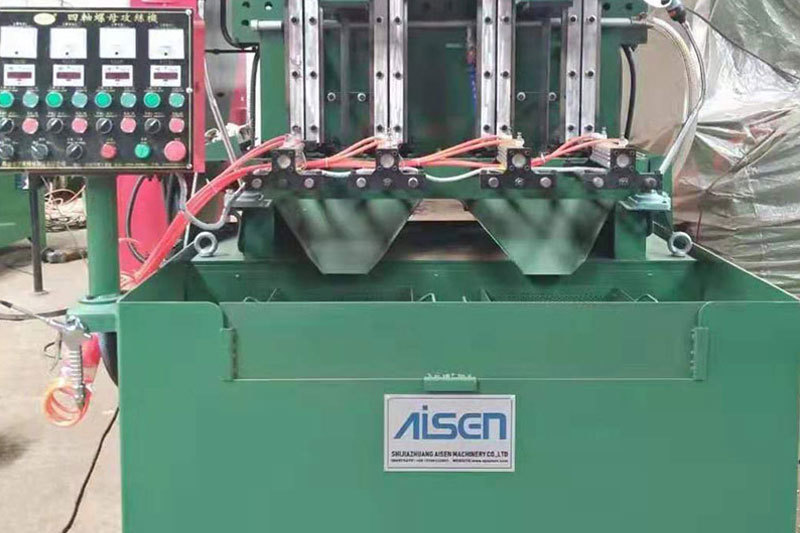
AISEN Four axis nut tapping machine ready for shipment to Russia
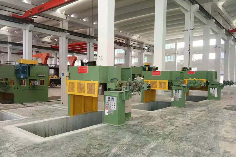
AISEN machinery inverted wire drawing machine
MESSAGES
We will contact you within one working day. Please pay attention to your email.
Qucik Link
Contact
Phone: +86-15100123091
E-mail: info@sjzaisen.com
Address: No.41 Zhaiying South Street, Yuhua District, Shijiazhuang City, Hebei Province China