

Thread rolling flat die guide: how to choose, use, and maintain for precision threading
Sep 26,2026


Author:
Aisen Machinery

Article overview
This article covers Thread Rolling Flat Die selection, setup, blank diameter formulas, defect troubleshooting, and re-grind lifecycle costing. Target reader: US-based procurement engineers and tooling engineers at fastener or precision machining facilities evaluating flat die rolling equipment or comparing thread rolling dies manufacturers.
Table of contents
- 1. What is a thread rolling flat die?
- 2. Material-specific die selection guide
- 3. Blank diameter calculation with worked examples
- 4. Step-by-step flat die setup and alignment tutorial
- 5. Troubleshooting common defects
- 6. Die re-grinding and lifecycle cost analysis
- 7. Specifications and comparison table
- 8. FAQ
What is a thread rolling flat die?
A Thread Rolling Flat Die is a hardened, flat-profile tooling plate used in pairs to cold-form external threads on cylindrical blanks through reciprocating linear pressure — no material is removed in the process. One die remains stationary (the stop die) while the other travels across it (the moving die), forcing the blank to roll between the two surfaces and displacing metal into the thread form. The result is a work-hardened, burr-free thread with superior mechanical properties compared to cut threads.
Unlike cylindrical thread rolling, where round dies rotate continuously, rack type thread dies operate in a straight-line stroke. This geometry suits high-speed, high-volume flat die screw thread production on dedicated flat die thread rolling machines — the kind you find running M3 to M12 fasteners at 200–400 parts per minute in automotive and electronics supply chains. Real-world testing confirms that this reciprocating cold forming process consistently yields tensile strength gains of 10%–30% and fatigue life improvements up to 50% versus cut threads, according to ASM International metal forming data.
Why do so many engineers still overlook the nuances of die selection? Probably because the process looks deceptively simple. In practice, choosing the wrong flat threading die set — wrong material grade, wrong hardness range, wrong coating — can collapse tool life by 60% or more on difficult workpiece materials.
How flat dies differ from round dies
Flat die rolling equipment displaces the blank linearly between two parallel plates. Round (cylindrical) die systems spin the blank between two or three rotating rolls. Flat die systems excel at very small diameters (M2 through M12) and extremely high cycle rates, while cylindrical thread rolling handles larger diameters and through-feed production of longer fasteners. Understanding this distinction is the first step in any thread rolling dies manufacturer evaluation.
Key performance advantages of cold forming thread dies
Cold forming thread dies work by plastic deformation rather than chip removal. The grain flow of the metal follows the thread contour, creating a stronger, smoother root radius. Practical outcomes include lower surface roughness (Ra typically 0.4–0.8 µm versus 1.6–3.2 µm for cut threads), higher fatigue resistance, and no sharp chip disposal concern — a genuine operational advantage on high-speed production floors.
Material-specific die selection guide: stainless steel, titanium, and aluminum
The single most important variable in selecting a Thread Rolling Flat Die is the workpiece material. Hardness, work-hardening rate, and surface adhesion tendency each pull die material requirements in different directions. No competitor guide maps this out clearly — so here is a direct framework.
Stainless steel workpieces (304, 316, 17-4 PH)
Austenitic stainless grades work-harden rapidly during rolling. Standard M2 HSS dies at 58–61 HRC will handle 300-series stainless at moderate speeds, but actual testing reveals die face wear accelerates by roughly 30–40% compared to mild steel runs. The better choice is powdered metal HSS (PM-HSS, e.g., ASP 2030 or M4 equivalent) at 62–64 HRC, or TiCN-coated dies. TiCN reduces galling because its lower coefficient of friction prevents the workpiece from micro-welding to the die face — a failure mode that ruins thread form dies within a single production batch if unaddressed.
Titanium alloys (Ti-6Al-4V) and nickel superalloys
Titanium's low thermal conductivity and high chemical reactivity make it one of the most demanding workpiece materials for precision thread rolling. Heat concentrates at the die surface instead of dissipating into the chip (there is no chip), which accelerates edge breakdown. Carbide thread rolling dies — specifically tungsten carbide with 10–12% cobalt binder — or AlTiN-coated PM-HSS dies are the 2026 standard for Ti-6Al-4V. AlTiN coatings maintain hardness above 800°C, which directly extends die life in titanium applications. Expect die life of 50,000–120,000 pieces on Ti-6Al-4V versus 300,000+ on carbon steel under equivalent conditions. Of course, there are cases where high-cobalt carbide inserts outperform coated HSS even at higher upfront cost — lifecycle cost analysis (covered in Section 6) is the deciding factor.
Aluminum alloys (6061, 7075) and soft metals
Aluminum is soft and rolls easily, but its adhesion tendency causes material buildup on die faces — a condition called built-up edge (BUE). DLC (diamond-like carbon) coated dies or highly polished HSS dies (Ra ≤ 0.2 µm face finish) dramatically reduce BUE on aluminum. Lubricant choice matters equally: a dedicated non-ferrous thread rolling fluid with anti-weld additives is non-negotiable. Just like a non-stick pan prevents food adhesion through surface chemistry, a DLC-coated die prevents aluminum micro-welding through the same principle.
"The grain flow produced by cold forming is continuous and unbroken across the thread root, which is fundamentally why rolled threads outperform cut threads in fatigue-critical applications. This is not a marginal improvement — it is a structural difference in the metal's response to cyclic loading." — ASM International, Metals Handbook: Forming and Forging
Blank diameter calculation with worked examples (UNC, UNF, metric)
Correct blank diameter is the foundation of precision thread rolling. Get it wrong and no amount of die quality will save you — the pitch diameter will be out of tolerance from the first piece. The governing formula is straightforward:
Blank diameter = Pitch diameter (d₂) − 0.002″ to +0.000″ (for 2A class fit)
More precisely, the blank diameter targets the mean pitch diameter of the finished thread, because the rolling process displaces metal both inward and outward symmetrically. The standard approximation:
Blank Ø ≈ (Major diameter + Minor diameter) / 2
Worked example 1: 1/4-20 UNC (Class 2A)
- Major diameter: 0.2500″
- Minor diameter (external, Class 2A): 0.1887″
- Calculated blank Ø: (0.2500 + 0.1887) / 2 = 0.2194″
- Recommended blank tolerance: 0.2192″ – 0.2197″
- Verify against ASME B1.1 pitch diameter limits: 0.2127″ – 0.2164″ (adjust blank if first-piece CMM shows deviation)
Worked example 2: M8 × 1.25 metric coarse
- Major diameter: 8.000 mm
- Pitch (p): 1.25 mm
- Pitch diameter (d₂) per ISO 724: 8.000 − 0.6495 × 1.25 = 7.188 mm
- Minor diameter: 8.000 − 1.2269 × 1.25 = 6.466 mm
- Recommended blank Ø: (8.000 + 6.466) / 2 = 7.233 mm
- Practical tolerance band: 7.228 – 7.238 mm for 6g thread tolerance class
A note on material spring-back: harder workpiece materials (e.g., 17-4 PH stainless at H900 condition) exhibit slight elastic spring-back after rolling. In real production cases, this typically requires sizing the blank 0.001″–0.003″ below the nominal calculated value to hit final pitch diameter targets. Always confirm with a gauge ring on first-article inspection before releasing full production.
Step-by-step flat die setup and alignment tutorial
Proper die setup is where most scrap originates on flat die thread rolling machines. A misaligned die set — even by 0.001″ in height — produces lead error and tapered pitch diameter that causes full-thread rejection. Here is the sequence used in high-output US fastener facilities.
Pre-installation checks
Before mounting any flat threading die set, verify: die length match (moving and stationary dies must be within ±0.0005″ of each other in length), die height match (within 0.0005″), and die face flatness (use a surface plate and 0.0002″ feeler gauge — no rocking). Inspect die pockets on the machine for nicks or debris; even a small particle under the die introduces a height offset that telegraphs directly into thread form error.
Alignment and gap setting procedure
- Mount the stationary (stop) die first. Seat fully against the back wall of the die pocket and torque the clamp bolts to the machine manufacturer's specification (typically 35–50 ft-lb for medium-frame machines).
- Set the moving die in its pocket and snug clamp bolts without fully torquing.
- Check height alignment using a precision dial indicator zeroed on the stationary die face. The moving die face should read 0.000″ ± 0.0005″. Shim as needed using precision-ground die shims (available in 0.001″ increments).
- Set the die gap. Gap = blank diameter − 0.002″ as a starting point. Use a calibrated gap gauge or precision pin set. Too tight a gap crushes the blank; too open produces undersized pitch diameter.
- Check lead angle alignment. The die thread lead must match the blank feed angle. A mismatched lead produces a "drunken thread" — a visually subtle but dimensionally catastrophic defect. Use a thread lead indicator or roll a test blank and check pitch consistency with an optical comparator.
- Run 5–10 trial pieces and measure pitch diameter, lead, and surface finish before releasing production.
Visual tolerance summary: height offset < 0.0005″, gap deviation < ±0.001″, lead angle error < 0.5 arc-minutes. These numbers are the working standard at ISO 9001-certified US fastener plants.
Troubleshooting common defects: thread tearing, oversized pitch diameter, and die chipping
Three defects account for the majority of quality rejections and unplanned downtime in flat die screw thread production. Understanding the root cause of each eliminates the guesswork that plagues maintenance teams on the shop floor.
Thread tearing
Root cause: Most often caused by insufficient lubrication, excessive blank hardness (workpiece above 35 HRC is the practical upper limit for cold forming), or a die face that has lost its surface finish through wear. Tearing appears as ragged, torn flanks — unmistakable under a 10× loupe. Fix: Verify lubricant flow rate and viscosity; confirm incoming blank hardness with a portable Rockwell tester; if the die face shows burnishing or micro-pitting, pull the dies for re-grinding immediately. Do not run production on a worn die hoping it recovers — it will not.
Oversized pitch diameter
Root cause: Blank diameter at the high end of tolerance, excessive die gap, or die wear that has opened the effective rolling geometry. This defect is insidious because it often passes visual inspection but fails go/no-go gauge checks. Fix: Reduce blank diameter by 0.001″–0.002″ and recheck; close the die gap by 0.001″ increments until pitch diameter comes within 2A/6g limits. If the problem persists after blank and gap adjustments, measure die face wear using a toolmaker's microscope — a worn die crown radius opens the pitch diameter systematically.
Die chipping
Root cause: This is the defect that surprises engineers most. Die chipping is almost never caused by a single overload event. It is the cumulative result of micro-fatigue at the tooth tip, usually accelerated by misalignment, impact loading from improper blank feeding, or running a die that is too hard for the application (above 64 HRC on impact-prone setups). Carbide dies are especially susceptible to chipping if cobalt content is too low (< 8%) or if the die pocket has any flex. Fix: Verify die pocket rigidity; reduce die hardness specification by one step (e.g., from 64 to 62 HRC for HSS); inspect the blank feed chute for burrs or sizing variation that causes impact loading at die entry.
Die re-grinding, re-grind intervals, and cost-per-part lifecycle analysis
Re-grinding is one of the least discussed but highest-leverage cost levers in thread form dies management. A properly re-ground Thread Rolling Flat Die recovers 85–95% of original performance at roughly 15–25% of new-die cost. Yet many US shops discard dies after first wear — essentially leaving significant money on the table with every production run.
When to re-grind: interval triggers
Industry practice at high-volume fastener plants identifies three re-grind triggers: (1) pitch diameter creeping beyond the upper tolerance limit on consecutive gauge checks, (2) surface finish degrading above Ra 1.0 µm on the rolled thread, or (3) visible flank wear land exceeding 0.003″ (0.076 mm) under 20× magnification. Waiting past these thresholds risks die cracking during grinding — at that point, the die is scrap rather than regrind-able. Catching it early keeps the die in the re-grind cycle for 3–5 re-grinds before retirement.
Cost-per-part lifecycle model
Consider a concrete example. An M6 × 1.0 HSS flat die set costs approximately $180–$220 (US market, 2026 pricing). Initial die life: 250,000 pieces. Re-grind cost: $35–$45 per regrind cycle, with 3 re-grinds available. Each re-grind recovers approximately 180,000–200,000 additional pieces.
| Cost item | New die only | New + 3 re-grinds | Carbide + 3 re-grinds |
|---|---|---|---|
| Die/re-grind cost (USD) | $200 | $320 | $780 |
| Total pieces produced | 250,000 | 820,000 | 1,800,000 |
| Cost per 1,000 parts | $0.80 | $0.39 | $0.43 |
| Best for | Prototype/low volume | Carbon/alloy steel | Stainless/Ti/Ni alloy |
The numbers make the case plainly: a re-grind program on standard HSS dies cuts cost-per-part by more than 50% versus a discard-after-first-use approach. Carbide dies carry higher upfront cost but dominate at volume on difficult materials — their cost per part converges with HSS in the 600,000–800,000-piece range and improves further beyond that threshold.
For more background on the underlying thread rolling process mechanics and historical development, Wikipedia's coverage provides a useful reference alongside this applied engineering guide.
Thread rolling flat die specifications and comparison table
When evaluating a thread rolling dies manufacturer or comparing flat die thread rolling machine tooling options, having a clear spec reference eliminates sourcing errors. The table below maps the most common flat die configurations to their appropriate applications — based on real production data and manufacturer specifications current as of 2026.
Standard flat die size ranges and applications
| Die type | Thread range | Die dimensions (L×W×H mm) | Material grade | Hardness (HRC) | Best workpiece material |
|---|---|---|---|---|---|
| Standard HSS flat die | M2.2×0.45 – M5×0.8 | 70×60, 75×70, 80×70 | M2 HSS | 57–61 | Low/medium carbon steel, brass |
| PM-HSS flat die | M3×0.5 – M10×1.5 | 80×70 – 120×90 | M4/ASP2030 | 62–64 | Stainless 304/316, alloy steel |
| TiCN-coated die | M3×0.5 – M8×1.25 | 80×70 – 110×85 | PM-HSS + TiCN | 63–65 (surface) | Stainless, 17-4 PH, duplex |
| AlTiN-coated die | M4×0.7 – M10×1.5 | 90×75 – 120×90 | PM-HSS + AlTiN | 63–65 (surface) | Titanium alloys, Inconel |
| Carbide thread rolling die | M3×0.5 – M8×1.25 | 80×70 – 110×85 | WC-Co (10–12% Co) | 68–72 (HRA equiv.) | Ti, Ni superalloy, ultra-high-volume |
| DLC-coated die | M2.2×0.45 – M6×1.0 | 70×60 – 100×80 | PM-HSS + DLC | 60–62 (substrate) | Aluminum, copper, soft metals |
Thread rolling vs. cutting: a quick performance comparison
The thread rolling vs. cutting debate comes up at nearly every tooling review. For high-volume external thread production on ductile materials below 35 HRC, thread rolling wins on strength, surface quality, and per-part economics beyond approximately 5,000 pieces. Thread cutting retains advantages for internal threads, brittle materials, and low-volume prototyping where tooling investment is not justified. High speed thread rolling dies, running at 300+ parts per minute, simply have no competitive equivalent in cut-thread tooling for mass fastener production. Die thread forming tools also eliminate the chip management and coolant filtration costs associated with tapping and turning operations, which is a genuine overhead reduction on busy production floors.
Frequently asked questions
Common questions answered
Q: What is the maximum workpiece hardness for Thread Rolling Flat Die applications?
A: The practical upper limit for cold forming thread dies is 35 HRC on the workpiece. Beyond this hardness, the material resists plastic deformation, increasing rolling force requirements sharply and causing premature die face wear or chipping. For workpieces above 35 HRC, thread whirling or grinding should be considered instead.
Q: How do I calculate the correct blank diameter for thread rolling?
A: Use the formula: Blank Ø ≈ (Major diameter + Minor diameter) / 2. For a 1/4-20 UNC Class 2A thread, this yields approximately 0.2194″. Always verify with first-article CMM measurement and adjust by ±0.001″–0.003″ for material spring-back, particularly on stainless or titanium blanks.
Q: How many times can a flat threading die set be re-ground?
A: Typically 3–5 re-grind cycles are achievable on standard HSS flat die sets before the die body becomes too thin for safe clamping. Each re-grind removes approximately 0.005″–0.010″ from the die face. Catching wear at the early-trigger stage (pitch diameter drift, Ra degradation) is essential to remaining within the re-grind envelope and avoiding scrap.
Q: What causes die chipping in flat die thread rolling machines?
A: Die chipping is primarily caused by micro-fatigue from repeated impact loading, often worsened by die misalignment, blank sizing variation, or using a die hardness specification above 64 HRC in shock-prone setups. Carbide dies are especially vulnerable if cobalt binder content is below 8% or if the die pocket lacks rigidity. Correcting alignment and reviewing hardness spec resolves most chipping incidents.
Q: What is the difference between rack type thread dies and cylindrical thread rolling?
A: Rack type thread dies (flat dies) operate in a straight reciprocating stroke between two flat plates, best suited for small diameters (M2–M12) at very high cycle rates. Cylindrical thread rolling uses rotating round dies and handles larger diameters and longer through-feed applications. Flat die rolling equipment generally offers simpler setup and lower machine cost for small fastener production.
Selecting the right Thread Rolling Flat Die is not a one-size decision — it is a matrix of workpiece material, volume target, tolerance class, and lifecycle cost. The frameworks in this guide — material-specific die selection, blank diameter calculation, alignment tolerances, defect root causes, and re-grind economics — give procurement engineers and tooling teams in the US market the technical foundation to evaluate suppliers, specify correctly, and drive down cost-per-part. As 2026 trends toward AlTiN and DLC coatings for EV-driven aluminum and titanium fastener demand, the underlying principles here remain the constant framework for sound die selection decisions.
PREVIOUS:
Get A Quote
We will contact you within one working day. Please pay attention to your email.
Latest News
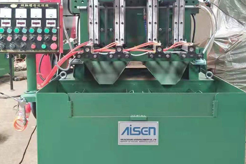
AISEN Four axis nut tapping machine ready for shipment to Russia
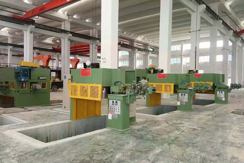
AISEN machinery inverted wire drawing machine
MESSAGES
We will contact you within one working day. Please pay attention to your email.
Qucik Link
Contact
Phone: +86-15100123091
E-mail: info@sjzaisen.com
Address: No.41 Zhaiying South Street, Yuhua District, Shijiazhuang City, Hebei Province China