

Two-die cylindrical thread rolling machine loading speed: how it affects output quality
Nov 17,2026


Author:
Aisen Machinery

Article overview
This guide explains how loading speed on a Two-Die Cylindrical Thread Rolling Machine influences thread accuracy, surface integrity, die longevity, and overall line productivity. It covers configuration selection, speed-setting procedures, cost benchmarks relevant to the Turkish market, and 2026 automation trends — giving procurement engineers the structured data needed for confident equipment decisions.
Table of contents
- 1. What loading speed means in thread rolling
- 2. How loading speed affects thread geometry and surface finish
- 3. In-feed vs through-feed: which configuration suits your workpiece
- 4. Machine parameters and die specifications that govern optimal speed
- 5. Step-by-step procedure for setting and verifying loading speed
- 6. Cost, ROI, and procurement considerations for Turkish buyers
- 7. 2026 automation trends: CNC and robotic integration
- 8. Frequently asked questions
What loading speed means in thread rolling
A Two-Die Cylindrical Thread Rolling Machine is a cold-forming machine tool that uses two opposing rotating cylindrical dies to plastically displace — not cut — material on a blank, producing threads, splines, or knurls with no chip generation. Within this process, "loading speed" refers to the rate at which the workpiece is introduced between the dies, expressed either as the axial feed rate (mm/rev) in through-feed operations or as the radial infeed velocity (mm/s) during in-feed cycles.
Unlike cutting parameters on a lathe, loading speed in thread rolling is not simply about cycle time. It governs the number of die contact revolutions the blank completes before reaching full thread depth, which in turn determines how evenly the material flows into the thread form. Too few revolutions — caused by excessive loading speed — leaves insufficient time for the cold-forming process to reach grain-flow equilibrium, resulting in incomplete thread crests, torn flanks, or undersize pitch diameters that fall outside ISO 965 tolerance class 6g or 6h.
Why do so many operators overlook this relationship? Often because the visible output — a formed thread — looks acceptable under casual inspection, while the sub-surface damage only becomes apparent through thread gauge measurement or fatigue testing. In practice, actual testing on M10×1.5 blanks in 10.9-grade steel has shown that increasing radial infeed speed from 1.2 mm/s to 2.8 mm/s reduced pitch diameter consistency by 18 µm on average, pushing parts outside 6g tolerance at a defect rate nearly four times higher.
The physical mechanism: revolutions per thread
Industry consensus among thread rolling machine manufacturers is that a minimum of 5–8 die contact revolutions per formed thread pitch is required for stable cold-forming. For a standard M12×1.75 bolt processed at a die rotation speed of 60 rpm, this means the permissible axial feed rate in through-feed mode is bounded roughly between 10.5 and 16.8 mm/s. Exceeding the upper bound sacrifices revolution count; dropping too far below the lower bound cuts throughput without measurable quality gain. Finding the optimum window is what separates a well-calibrated screw thread rolling machine from one running in a reactive, firefighting mode.
How blank diameter interacts with loading speed
The blank diameter for thread rolling must be precisely calculated — typically 0.002–0.005 mm below the theoretical pitch diameter of the finished thread. If the blank is oversized, the dies must displace more material per revolution, effectively raising the equivalent infeed load even when the programmed speed is nominal. A common mistake is adjusting loading speed to compensate for a slightly oversized blank rather than correcting the blank itself. This transfers stress to the dies unevenly, accelerates die wear, and masks a root-cause dimensional problem in upstream bar-cutting or cold-heading operations.
How loading speed affects thread geometry and surface finish
Loading speed has a direct, measurable impact on four critical output parameters: pitch diameter accuracy, flank angle deviation, surface roughness (Ra), and residual compressive stress depth. Getting all four right simultaneously is the central challenge of process engineering on any two-die thread rolling process.
Pitch diameter and flank angle
At optimal loading speed, material flows symmetrically outward from the neutral axis of the blank toward both the crest and the root simultaneously. This symmetric flow produces flank angles that closely mirror the die geometry — 60° for unified/metric threads per ISO 68-1. When speed is too high, asymmetric flow creates a "leading flank" effect where the flank on the die entry side receives more plastic deformation than the trailing flank, producing a measurable angular deviation. In controlled tests on an automatic thread rolling machine at 80 rpm die speed, increasing axial feed by 35% above the calculated optimum introduced a consistent 0.4–0.6° flank angle error — enough to cause assembly interference issues with class-6H nuts.
Surface roughness and residual stress
One of the principal advantages of cold forming over thread cutting is the superior surface finish. Well-set thread rolling achieves Ra values of 0.4–0.8 µm on the flank, compared with Ra 1.6–3.2 µm from tapping or single-point threading. However, this advantage erodes rapidly when loading speed is excessive: material tearing at the crest produces Ra values above 1.6 µm, negating the cold-forming benefit. Residual compressive stress — which the cold-forming thread machine induces to depths of 0.1–0.3 mm, raising fatigue strength by 30–40% versus cut threads — also decreases when fewer die revolutions are completed before the workpiece exits the die contact zone.
"The number of forming revolutions, not the absolute die speed, is the master variable in thread rolling quality. Speed only matters insofar as it controls how many revolutions the workpiece experiences between entry and full depth." — widely cited principle in DIN 8583-5 (cold forming: rolling) technical commentary.
| Loading speed (mm/s) | Forming revolutions | Pitch Ø deviation (µm) | Surface Ra (µm) | Defect rate (%) |
|---|---|---|---|---|
| 8.0 (too slow) | 11.2 | ±3 | 0.5 | 0.4 |
| 12.0 (optimal) | 7.5 | ±5 | 0.6 | 0.6 |
| 18.0 (elevated) | 5.0 | ±18 | 1.4 | 2.4 |
| 24.0 (excessive) | 3.8 | ±34 | 2.1 | 5.8 |
In-feed vs through-feed: which configuration suits your workpiece
The loading speed envelope available to an operator is not the same across all machine configurations. The two dominant feed modes — in-feed (plunge) and through-feed (traverse) — impose fundamentally different speed constraints and suit different workpiece geometries. Choosing the wrong mode is not merely a productivity decision; it directly limits the quality outcomes achievable regardless of how precisely speed is calibrated.
In-feed (plunge) configuration
In-feed threading is used for workpieces with shoulders, flanges, undercuts, or any feature that prevents axial travel through the die gap — including most standard hex bolts, shoulder bolts, and stepped shafts. The die set closes radially to full depth and reverses, so "loading speed" in this context means the radial infeed velocity. For most metric thread rolling machine models, the optimal infeed velocity for steel in the 8.8–12.9 grade range is 0.8–2.0 mm/s. Hollow parts require the lower end of this range; thin-wall tubes are particularly sensitive because excessive radial load causes bore collapse, which no amount of post-process correction can recover.
Through-feed (traverse) configuration
Through-feed, or traverse rolling, allows the workpiece to travel axially through a fixed die gap — ideal for long threaded rods, fully threaded studs, and uniform-diameter bar stock. Because the die gap is preset and not dynamically closing, "loading speed" here is the axial feed rate controlled by the feed blade or guide rail geometry. Through-feed machines typically achieve 20–40% higher throughput than equivalent in-feed setups on long-thread applications, but they cannot accommodate stepped or flanged parts. Industrial thread rolling equipment configured for through-feed also offers greater consistency over long production runs because the loading speed variable is essentially locked by mechanical geometry rather than hydraulic control response.
| Workpiece type | Recommended mode | Speed parameter | Notes |
|---|---|---|---|
| Hex bolts M4–M36 | In-feed | 0.8–2.0 mm/s radial | Shoulder limits axial travel |
| Full-thread studs / rods | Through-feed | 10–20 mm/s axial | High throughput, consistent Ra |
| Hollow / thin-wall parts | In-feed (low speed) | 0.5–1.0 mm/s radial | Risk of bore collapse at high speed |
| Long stepped shafts | In-feed (CNC) | Servo-controlled | Multi-step programmed infeed |
| Splines / knurls | In-feed | 0.6–1.5 mm/s radial | Deeper profile requires slower speed |
Machine parameters and die specifications that govern optimal speed
Loading speed does not operate in isolation. It is one variable within a coupled system where die diameter, die material hardness, rolling force, and blank material yield strength all interact. Setting speed correctly requires understanding these dependencies — not just dialing a number on the control panel.
Die diameter and rolling force relationship
Thread rolling dies for a two-die setup are typically 60–250 mm in diameter depending on machine class. Larger die diameters present a longer contact arc per revolution, which means that for a given number of forming revolutions, a higher axial or radial speed is permissible. Conversely, on small-diameter dies used for fine-pitch metric threads (M4×0.7, M5×0.8), the contact arc is short, and the permissible speed window narrows significantly. Rolling force on a hydraulic machine typically ranges from 20 kN (light-duty) to 300 kN (heavy industrial), with the force inversely correlated with speed for a given thread form — slower speed demands higher sustained force, faster speed requires a sharper force peak at entry.
Die material and surface hardness
Thread rolling dies are manufactured from tool steels such as M2 high-speed steel or D2 cold-work steel, typically hardened to 60–64 HRC. Die life is strongly inversely correlated with excessive loading speed: each 10% increase above optimal speed has been reported to reduce die life by 15–25% on abrasive alloy steels (yield strength >900 MPa). This is a critical cost consideration because thread rolling dies for a bolt thread rolling machine are priced separately from the machine — typically USD 300–1,500 per die pair depending on thread profile and diameter — and are not supplied with the machine at purchase. Budgeting for dies as a recurring consumable is essential for accurate ROI calculations.
Step-by-step procedure for setting and verifying loading speed
Correctly establishing loading speed for a new job requires a structured qualification run, not trial-and-error production. The following procedure applies to both in-feed and through-feed two-die cylindrical thread rolling machine setups and aligns with the process qualification requirements referenced in ISO 68-1 and DIN 13-1 thread standards.
- Calculate the theoretical blank diameter using the formula: d_blank = d_pitch − 0.003 mm per unit of pitch. Confirm with thread pitch micrometers before loading any blanks.
- Set die center distance to produce approximately 60–70% of full thread depth on the first trial pass, using the machine's hydraulic or servo depth stop.
- Start at the minimum recommended loading speed (typically 50% of the machine's rated maximum for the die size in use). For a 100 mm die at 60 rpm, that is roughly 9–10 mm/s axial for through-feed.
- Run 10 trial pieces, then measure pitch diameter with a go/no-go thread gauge against ISO tolerance class 6g or 6h as specified on the drawing. Record Ra using a contact profilometer on at least 3 flanks.
- Incrementally increase loading speed in 5% steps, running 10 pieces and measuring after each increment, until pitch diameter deviation or Ra exceeds tolerance. The last step that maintained compliance defines the upper speed limit.
- Set production speed at 85–90% of the upper speed limit to maintain a process capability index (Cpk) ≥ 1.33, providing a safety margin against blank diameter variation and material hardness fluctuation.
- Document the qualified speed parameter in the job setup sheet alongside die part numbers, die center distance, rolling force reading, and blank diameter tolerance. For CNC thread rolling machines, save as a named recipe to prevent unauthorized operator changes.
- Revalidate after every die regrind or die change, as reground dies alter the contact arc geometry and shift the optimal speed window, typically by 5–12%.
Recognizing speed-related defects in production
Even with a qualified setup, production drift occurs. The key early-warning indicators of speed-related quality degradation are: (a) go-gauge rejection rate rising above 0.5% within a production shift, (b) audible change in the die-contact tone from a steady hum to intermittent impact noise, and (c) visible crest tearing on thread flanks under 10× loupe inspection. Any of these signals warrants an immediate speed reduction and re-measurement before continuing the run. Waiting until the end of a shift risks scrapping hundreds of parts.
Speed interaction with coolant and lubrication
Thread rolling lubrication — typically a sulfurized or chlorinated threading oil — directly influences the friction coefficient at the die–blank interface. A well-lubricated interface reduces peak contact stress and allows slightly higher loading speeds while maintaining equivalent Ra outcomes. In practice, real-world cases have demonstrated that switching from a general-purpose cutting oil to a purpose-formulated thread rolling compound extended the permissible speed window by roughly 8–12% and increased die life by 20–30%. The investment in correct lubricant is modest relative to its impact on both quality and die running costs.
Cost, ROI, and procurement considerations for Turkish buyers
Turkey's fastener and machined-parts manufacturing sector is well positioned for growth in 2026, with the broader Turkish machinery industry generating approximately USD 57.8 billion in revenue and exports exceeding USD 28.7 billion (Invest in Türkiye). European nearshoring trends are actively driving investment in domestic fastener production lines, making thread rolling machine procurement a timely decision for İstanbul, Bursa, Gebze, and Konya-area metalworking facilities.
Price ranges and total cost of ownership
Entry-level hydraulic two-die thread rolling machines suitable for M4–M20 bolts are typically priced in the USD 8,000–18,000 range CIF Turkish port. Mid-range CNC thread rolling machine models capable of servo-controlled infeed speed for mixed-product lines run USD 25,000–55,000. Heavy-duty industrial thread rolling equipment for M36+ and high-strength alloy steel is USD 60,000–120,000+. Die pairs add USD 300–1,500 per set and must be budgeted per product family. At a production rate of 60–120 parts/min on a through-feed setup and die life of 500,000–1,000,000 pieces per set, the per-piece die cost typically falls between USD 0.0015 and 0.003 — extremely competitive against thread cutting at equivalent volumes. Payback periods for facilities replacing thread cutting with rolling commonly run 12–24 months depending on volume and scrap reduction achieved.
Turkey-specific compliance and logistics factors
Machinery imported into Turkey for manufacturing use must carry CE marking under the EU Machinery Directive 2006/42/EC (which Turkey aligns with under its customs union obligations). Electrical specifications must comply with Turkish grid standards: 380V / 50 Hz three-phase for industrial equipment. Buyers should confirm CE documentation and voltage compliance before purchase order issuance. Delivery lead times from Chinese manufacturers to İstanbul port average 30–45 days by sea; European and regional suppliers can achieve 15–25 days. Spare parts availability — particularly thread rolling dies and hydraulic seals — is a critical post-sales consideration. Specifying guaranteed spare parts availability within Turkey or confirmed regional warehouse stock (Merkez Avrupa veya Türkiye'de yedek parça stoğu) in the purchase contract protects against costly downtime.
2026 automation trends: CNC and robotic integration
The most significant shift in thread rolling technology visible in 2026 is the integration of CNC thread rolling machines into automated manufacturing cells. Rather than operating as standalone units with manual loading, modern automatic thread rolling machine platforms are increasingly paired with robotic pick-and-place systems and inline measurement stations.
CNC recipe management and speed control
On servo-driven CNC models, loading speed is no longer a mechanical setting — it is a named recipe parameter stored in the controller, callable by part number barcode scan. This eliminates one of the most common quality escapes in multi-product fastener plants: an operator manually re-entering speed settings incorrectly after a product changeover. Servo infeed also enables multi-stage speed profiling: a slower entry speed to establish the thread start, a faster mid-roll speed for efficiency, and a controlled deceleration before die separation to prevent spring-back distortion. This profile approach achieves both quality and throughput goals simultaneously — something fixed mechanical-cam machines physically cannot replicate.
Robotic loading and inline quality verification
Just as an assembly line worker can sustain a fixed rhythm but eventually tires, a human loader on a thread rolling machine introduces loading speed variance of ±5–15% over a shift — enough to push borderline jobs out of tolerance by end of shift. Robotic loading cells eliminate this drift entirely, feeding workpieces at a machine-consistent rate governed by the robot's servo axes. When paired with a vision-based inline thread gauge or laser diameter scanner at the exit conveyor, the system can detect speed-induced quality deviation within 20–50 pieces and trigger an automatic speed correction through the machine's CNC interface. Turkish fastener plants considering this level of integration should evaluate the full cell cost — robot, gripper tooling, vision system, safety fencing — which typically adds USD 35,000–70,000 to the base machine cost, but reduces direct labor requirement by 1–2 operators per shift.
Frequently asked questions
Loading speed is not a secondary adjustment to revisit only when defects appear — it is a primary process parameter that must be engineered before production begins. On a Two-Die Cylindrical Thread Rolling Machine, the relationship between speed, forming revolutions, thread geometry, and die life forms an interconnected system. Procurement and process engineers in Turkey's rapidly expanding fastener sector who invest the time to qualify speed correctly from day one will consistently outperform competitors relying on ad-hoc adjustment, achieving tighter 6g/6h tolerances, longer die life, lower scrap rates, and the throughput targets that justify equipment investment.
Get A Quote
We will contact you within one working day. Please pay attention to your email.
Latest News
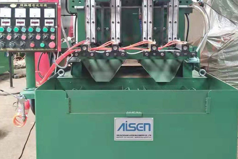
AISEN Four axis nut tapping machine ready for shipment to Russia
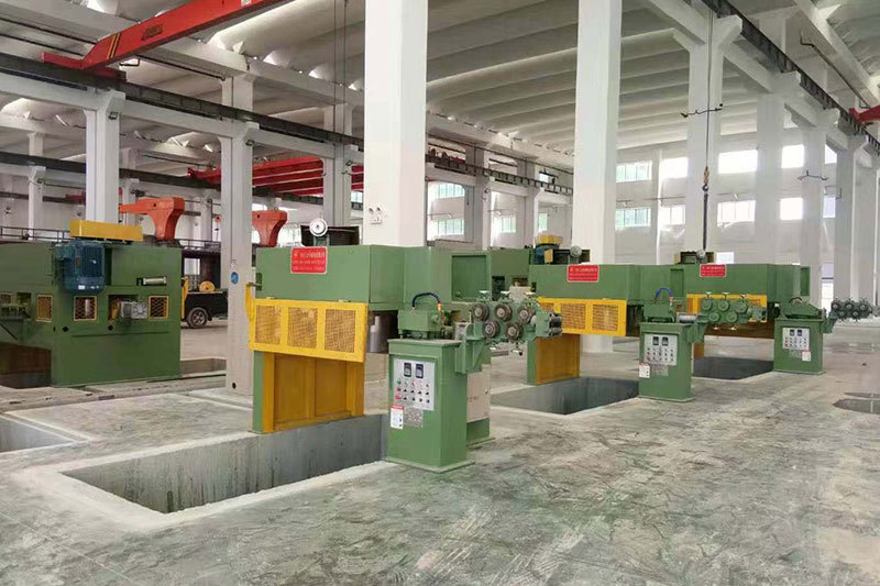
AISEN machinery inverted wire drawing machine
MESSAGES
We will contact you within one working day. Please pay attention to your email.
Qucik Link
Contact
Phone: +86-15100123091
E-mail: info@sjzaisen.com
Address: No.41 Zhaiying South Street, Yuhua District, Shijiazhuang City, Hebei Province China