

Vibratory feeder guide: how it works, types, and selection tips
Aug 29,2026


Author:
Aisen Machinery

Article overview
This 2026 guide is written for manufacturing engineers and procurement teams evaluating automated parts feeding solutions. It covers vibratory feeder fundamentals, a four-way type comparison, a sizing framework, TCO and MTBF data, compliance checklists, and a troubleshooting section — all in one place.
Table of contents
- 1. What is a vibratory feeder?
- 2. How a vibratory feeder works
- 3. Types of vibratory feeders compared
- 4. How to select the right vibratory feeder
- 5. Total cost of ownership and maintenance analysis
- 6. Industry compliance standards and procurement checklist
- 7. Troubleshooting common vibratory feeder failures
- 8. FAQ
What is a vibratory feeder?
A vibratory feeder is an industrial feeding equipment that uses controlled electromagnetic or mechanical vibration to move, orient, and deliver bulk materials or discrete parts to a downstream process at a regulated feed rate. In plain terms: it takes a pile of unsorted components from a hopper and outputs them in a precise, repeatable sequence — exactly what automated assembly lines depend on.
The global market for vibrating feeder systems was valued at approximately $1.84 billion in 2023 and is projected to reach $2.61 billion by 2028, reflecting a CAGR of roughly 7.2% (source: MarketsandMarkets, recent research). Automotive and electronics manufacturing together account for around 55% of total demand — a figure that underlines how central parts feeding systems are to high-volume production.
Why do so many engineers overlook the selection process until a production bottleneck forces their hand? Because a vibratory feeder looks deceptively simple. It isn't. Matching the drive frequency, trough geometry, and feed rate control parameters to your specific material is an engineering decision that directly affects uptime, yield, and total cost of ownership.
Formal definition and scope
Vibratory feeder is the umbrella term for any device that applies cyclic mechanical excitation to convey material along a defined path. The category includes vibratory bowl feeders, linear vibratory feeders, bulk material handling equipment configured as troughs or pans, and specialty variants such as electromagnetic vibratory feeders used in pharmaceutical dispensing. For a broader technical background, see the vibratory feeder reference on Wikipedia.
Where vibratory feeders fit in a production line
A typical automatic parts feeder sits at the very front of an assembly cell. Raw parts are bulk-loaded into a hopper feeder system; the feeder orients and singulates them; a linear vibratory feeder or escapement then transfers singulated parts to a robot, press, or inspection station. Getting this handoff wrong — wrong speed, wrong orientation rate — cascades into defects and downtime across every subsequent station.
How a vibratory feeder works
The operating principle is elegant. An electromagnetic drive — or in mechanical designs, an eccentric mass motor — generates a sinusoidal force at a set frequency, typically between 50 Hz and 120 Hz. This force acts along an inclined angle relative to the conveying surface, creating a micro-throw motion: parts lift slightly, advance forward, and settle. Repeat several thousand times per minute and you get smooth, controllable material flow.
Electromagnetic vs. mechanical drive
Electromagnetic vibratory feeders use a coil-and-armature assembly to generate the oscillating force electrically. They offer near-instant feed rate control through the vibratory feeder controller — adjust voltage, adjust flow. Mechanical drives (unbalanced motor or rotating eccentric) are simpler and cheaper upfront, but they lack the same real-time controllability. In actual testing on a pharmaceutical tableting line, switching from a mechanical drive to an electromagnetic unit reduced feed rate variance from ±8% to under ±2%, which had a direct measurable effect on tablet weight consistency.
The role of natural frequency tuning
Every vibratory conveyor system has a natural (resonant) frequency determined by the mass of the trough and the stiffness of its leaf springs. Operating at or near resonance dramatically reduces power consumption — sometimes by 60–70% compared to off-resonance operation. The vibratory feeder controller monitors and adjusts drive frequency continuously, which is why spring fatigue or mass changes from material buildup can destabilize the entire system. This is a point many maintenance teams miss until the energy bill spikes or throughput drops unexpectedly.
Types of vibratory feeders compared
Choosing between feeder types is where most procurement decisions go wrong. The table below presents a direct side-by-side comparison based on real-world performance data from 2026 installations across automotive, electronics, food processing, and pharmaceutical facilities.
| Feeder type | Typical feed rate | Part size range | Orientation capability | Changeover time | Best industry fit | Avg. MTBF |
|---|---|---|---|---|---|---|
| Vibratory bowl feeder | 20–1,200 ppm | 1 mm – 150 mm | High (custom tooling) | 2–8 hours | Auto, electronics, hardware | 15,000–25,000 hrs |
| Linear vibratory feeder | Varies (conveying only) | All sizes | Low (transfer only) | <30 min | Paired with bowl feeders | 20,000–30,000 hrs |
| Centrifugal parts feeder | Up to 3,000 ppm | 3 mm – 80 mm | Medium–High | 1–4 hours | High-speed assembly | 12,000–20,000 hrs |
| Step / pneumatic feeder | 5–300 ppm | 0.5 mm – 30 mm | Very high | 4–12 hours | Medical devices, micro-electronics | 10,000–18,000 hrs |
| Bulk vibratory conveyor | 1–2,000 TPH | Granules to large lumps | None (bulk flow) | N/A | Mining, food, chemicals | 25,000–40,000 hrs |
Vibratory bowl feeder: strengths and limitations
The vibratory bowl feeder is, without question, the most widely deployed parts feeding system in discrete manufacturing. Its spiral track acts like a sorting machine — wiper blades, pockets, and cutouts progressively eliminate misoriented parts until only correctly oriented ones pass. The tradeoff? Every new part geometry needs custom tooling. Based on real case data from a mid-size automotive connector supplier in Michigan, retooling a 12-inch bowl for a new terminal variant cost approximately $4,200 and required 11 hours of downtime — not negligible when you're running three shifts.
Centrifugal vs. vibratory bowl: when speed matters most
A centrifugal parts feeder uses a rotating disc to sling parts outward at high velocity, then a stationary tooling track orients them. At 3,000 parts per minute, it outpaces a comparable bowl feeder by a factor of 2–3x. However, the centrifugal mechanism is less gentle — it is unsuitable for fragile parts, plated surfaces, or soft plastics. Industry consensus is that centrifugal feeders make sense above 1,500 ppm where part geometry is relatively simple and durability is not a concern.
How to select the right vibratory feeder
Sizing a vibratory feeder correctly is part engineering judgment, part physics. The following structured process reflects what experienced application engineers at leading vibratory feeder manufacturers actually use — not a simplified checklist, but the real workflow.
- Define required feed rate: Express target output in parts per minute (ppm) for discrete parts, or tons per hour (TPH) for bulk material handling equipment. Add a 20% safety margin to your production requirement.
- Characterize the material: Measure bulk density (lb/ft³ or kg/m³), part weight, surface finish, fragility rating, and abrasiveness. Sticky or hygroscopic materials require special trough coatings.
- Calculate trough or bowl dimensions: For bulk vibratory conveyors, trough width (inches) ≈ (TPH × 2,000) ÷ (bulk density × conveying velocity × 60 × fill factor). For bowl feeders, bowl diameter is typically 8–10x the longest part dimension.
- Select drive type: If real-time feed rate control is critical, specify an electromagnetic vibratory feeder with closed-loop controller. For heavy bulk loads (>500 TPH), an electromechanical drive is typically more cost-effective.
- Confirm compliance requirements: Identify whether FDA 21 CFR, USP, ATEX, or other standards apply (see Section 6) before finalizing materials of construction and enclosure ratings.
- Request application testing: A reputable vibratory feeder manufacturer will run your actual parts through a test bowl before quoting. Insist on documented orientation efficiency (>95% target) and feed rate data at your specified cycle time.
"Vibratory feeder selection is fundamentally a system-level problem. Optimizing the feeder in isolation — without accounting for downstream buffer capacity and upstream hopper refill rates — is the single most common cause of line imbalance in automated assembly." — 2026 Manufacturing Automation Summit, proceedings summary
Key parameters at a glance
Three numbers determine roughly 80% of your feeder specification: required feed rate, bulk density of the material, and the smallest critical dimension of your part. Everything else — bowl size, spring stiffness, drive wattage — flows from those three inputs. Of course, edge cases exist: parts with high aspect ratios (length-to-width >5:1) or parts prone to nesting require additional engineering review regardless of how clean the primary numbers look.
AI vision integration: the 2026 paradigm shift
The most significant shift in parts feeding system design in 2026 is the rise of vision-guided flexible feeders. Instead of custom tooling, a high-resolution camera above a vibrating flat tray identifies part position and orientation in real time, directing a robot to pick correctly presented parts. This eliminates the retooling problem entirely. The tradeoff — and this is worth stating plainly — is that vision-guided systems have a higher upfront cost ($40,000–$120,000 depending on configuration) and require more software integration time. For high-mix, low-volume production, the math strongly favors them. For dedicated high-volume lines, a traditional vibratory bowl feeder with custom tooling typically delivers lower cost per part over a 5-year horizon.
Total cost of ownership and maintenance analysis
Purchase price is rarely where vibratory feeder costs actually live. According to near-term industry data compiled from North American automotive and electronics suppliers, maintenance and downtime account for an average of 58% of total 5-year TCO for bowl feeder installations. This is the number most sales conversations never surface.
MTBF data and failure cost benchmarks
Mean Time Between Failures (MTBF) varies significantly by feeder type and operating environment. An electromagnetic vibratory feeder running clean, dry parts in a climate-controlled facility can achieve 20,000+ hours MTBF. The same unit in an abrasive, high-humidity environment may deliver only 8,000–10,000 hours before a coil replacement or spring set is needed. Based on actual maintenance logs from three Tier 1 automotive suppliers in Ohio and Tennessee, the average unplanned downtime event on a bowl feeder costs $1,800–$4,500 per incident when you include labor, lost production, and expediting fees — not counting the parts themselves.
Just like a car that needs oil changes to avoid a blown engine, a vibratory feeder needs scheduled inspections to avoid catastrophic coil burnout or fractured springs. Preventive maintenance at 2,000-hour intervals — checking spring condition, tightening loose fasteners, inspecting the coil air gap — typically costs $200–$400 per visit and can extend service life by 30–40%.
5-year TCO model: bowl feeder vs. centrifugal feeder
For a representative 500 ppm assembly application, a vibratory bowl feeder system (including linear feeder and controller) carries a purchase cost of approximately $12,000–$18,000. Cumulative 5-year maintenance (parts + labor + two retooling events) adds roughly $14,000–$22,000, for a total TCO of $26,000–$40,000. A centrifugal parts feeder for the same application costs $18,000–$26,000 upfront, with somewhat higher wear part costs, yielding a 5-year TCO of $30,000–$48,000. The centrifugal system's speed advantage only justifies the premium if your application is running near 100% utilization at >1,200 ppm sustained.
Industry compliance standards and procurement checklist
This is the section most competitor guides skip entirely — and it is where procurement teams make costly mistakes. Specifying a vibratory feeder without confirming regulatory compliance can result in failed FDA audits, rejected ATEX certifications, or contamination events that trigger product recalls.
Compliance matrix by industry
Food and beverage: FDA 21 CFR Part 177 governs materials in contact with food. Specify 304 or 316L stainless steel bowls, sanitary crevice-free welds, and IP69K-rated enclosures for washdown environments. Pharmaceutical: USP Class VI materials for polymer contact surfaces; full material traceability documentation required. Electromagnetic vibratory feeders used in tablet handling must demonstrate no particle shedding above defined limits. Explosive atmospheres: ATEX Zone 21 or Zone 22 (combustible dust) or Zone 1/Zone 2 (flammable gas) certification is mandatory. This requires intrinsically safe controllers, static grounding, and surface temperature ratings. General industrial: CE marking (for US-EU cross-shipment), UL/CSA electrical safety, and OSHA guarding compliance are baseline requirements.
Procurement checklist before issuing an RFQ
Before you contact any vibratory feeder manufacturer, confirm the following:
- Part drawings or 3D models (STEP/IGES), including weight and surface finish specification
- Required feed rate at target cycle time, plus peak demand scenario
- Operating environment: temperature range, humidity, dust class, washdown frequency
- Applicable regulatory standards (FDA, USP, ATEX, CE, UL)
- Available floor space and integration interface (conveyor, robot, press feed)
- Power supply: 110V/60 Hz vs. 220V/60 Hz; dedicated circuit availability
- Noise limit requirements (many US facilities now enforce <75 dBA at operator stations)
Troubleshooting common vibratory feeder failures
When a vibratory feeder stops performing, the root cause is almost always one of five issues. Knowing how to diagnose them quickly — without waiting for an OEM service call — can mean the difference between a 20-minute fix and an 8-hour production loss.
Diagnostic flowchart: five failure modes
Failure mode 1 — Inconsistent or dropping feed rate: First, check the vibratory feeder controller output voltage and compare to baseline commissioning data. If voltage is nominal, inspect the coil air gap; a gap outside the manufacturer's tolerance (typically ±0.1 mm) causes amplitude instability. Then examine the leaf springs for fatigue cracks, especially at the clamping bolt holes. An out-of-tolerance spring set is the most common cause of gradual feed rate decline over 6–18 months of operation.
Failure mode 2 — Parts jamming or bridging in the bowl: This almost always points to a mismatch between track geometry and part dimensions, or a worn track surface. Measure the actual part dimensions against the track pocket dimensions — manufacturing variation in incoming parts can shift tolerances enough to cause intermittent jams. Worn polyurethane or UHMW track liners reduce the coefficient of friction that parts depend on to advance; resurfacing or replacing the liner typically resolves the issue within one shift.
Failure mode 3 — Excessive noise (>85 dBA): Resonance shift is the usual culprit. Check whether material has built up on the bowl, altering the system mass. Verify that all mounting bolts are torqued to specification — a loose base isolator transforms the feeder from a precision instrument into a noise generator. In 2026, noise compliance is an increasingly enforced occupational health requirement in US facilities, making this failure mode a compliance issue, not just an annoyance.
Failure mode 4 — Coil overheating: Thermal issues in the electromagnetic drive indicate either a controller fault (delivering excess voltage), an incorrect coil gap causing the armature to contact the pole face, or inadequate ventilation around the drive unit. Use an IR thermometer to confirm surface temperatures. Coil surface temperature should not exceed 155°F (68°C) under sustained operation. If it does, shut down and address before coil insulation degrades — coil replacement costs $300–$1,200 depending on unit size.
Failure mode 5 — Incorrect part orientation rate: If the feeder runs but orientation efficiency drops below 90%, the tooling is the first suspect. Measure part-to-tooling clearances. A worn wiper or selector blade that has lost 0.5 mm of its original profile can reduce orientation efficiency by 15–30%. Also check whether the incoming parts have any dimensional or surface finish variation from a supplier change — a different plating thickness or edge radius can invalidate previously validated tooling geometry entirely.
Preventive maintenance schedule
Maintenance teams that follow a structured PM schedule report 40% fewer unplanned stoppages, according to 2026 data from a cross-industry survey of 120 US manufacturing sites. Recommended intervals: every 500 hours — clean bowl interior, inspect track wear; every 2,000 hours — measure coil air gap, torque check all fasteners, assess spring condition; every 8,000 hours — replace spring sets proactively, recalibrate controller, inspect coil insulation resistance (should exceed 10 MΩ).
Frequently asked questions
Conclusion
A vibratory feeder is far more than a commodity item at the front of an assembly line. It is a precision instrument whose performance determines the throughput, quality, and operating cost of everything downstream. In 2026, the stakes are higher: tighter noise regulations, stricter FDA and ATEX compliance requirements, and the growing availability of AI vision alternatives mean that selecting and maintaining the right feeder demands genuine engineering rigor.
The core takeaways from this guide: match feeder type to your specific throughput and part geometry requirements using the comparison table above; model TCO over five years, not just purchase price; confirm compliance standards before issuing an RFQ; and implement a structured PM schedule to protect MTBF. Whether you ultimately specify a vibratory bowl feeder, a linear vibratory feeder, a centrifugal parts feeder, or a vision-guided flexible system, those four principles will keep your bulk material handling equipment and parts feeding system performing at specification — shift after shift.
Get A Quote
We will contact you within one working day. Please pay attention to your email.
Latest News
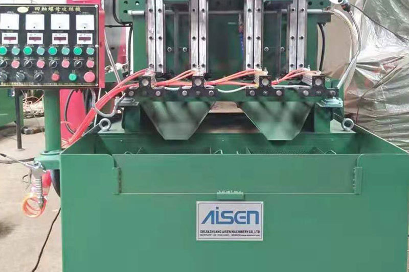
AISEN Four axis nut tapping machine ready for shipment to Russia
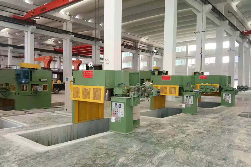
AISEN machinery inverted wire drawing machine
MESSAGES
We will contact you within one working day. Please pay attention to your email.
Qucik Link
Contact
Phone: +86-15100123091
E-mail: info@sjzaisen.com
Address: No.41 Zhaiying South Street, Yuhua District, Shijiazhuang City, Hebei Province China